
Noise reduction diversion grid

A technology of guide grille and noise reduction, applied in the field of noise reduction guide grille, can solve the problems of unsatisfactory noise reduction function of guide grille

Active Publication Date: 2021-03-16
FANS TECH ELECTRIC CO LTD
View PDF12 Cites 0 Cited by
  • Summary
  • Abstract
  • Description
  • Claims
  • Application Information

AI Technical Summary

Problems solved by technology

[0006] The purpose of the present invention is to provide a diversion grid, which is used to solve the defects of the unsatisfactory noise reduction function of the evenly distributed diversion grid in the existing design, effectively improve the air intake conditions of the fan under the condition of non-uniform inlet, and make the inside of the fan The flow is more reasonable to achieve the purpose of noise reduction

Method used


Image

  • Noise reduction diversion grid
  • Noise reduction diversion grid
  • Noise reduction diversion grid

Examples


Embodiment 1

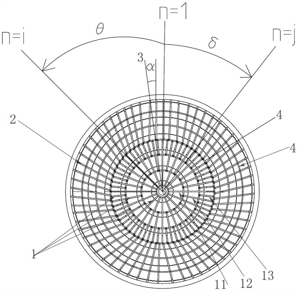
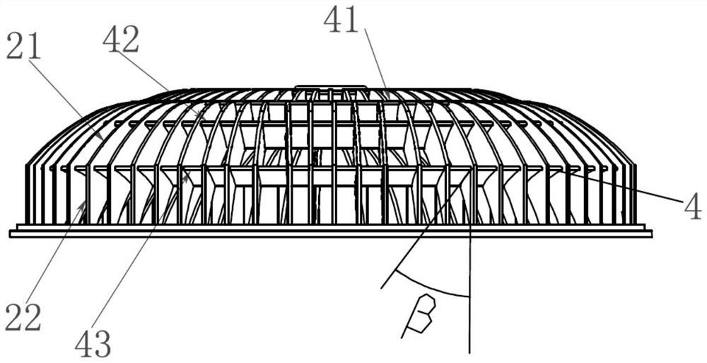
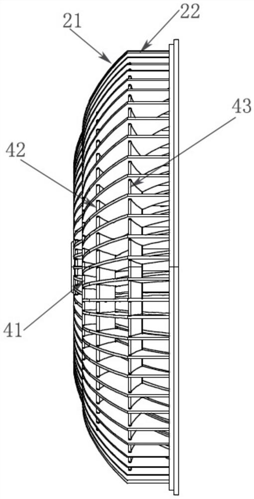
[0056] Such as Figure 1~3 As shown, a noise reduction diversion grid, the diversion grid has a grid structure, the grid structure includes:

[0057] Radial grids and circumferential grids 4, the radial grid extends radially along the diversion grid, and several radial grids are distributed along the circumference of the diversion grid at intervals. A number of coaxial circumferential gratings 4 are distributed at radial intervals with the axis of the diversion grid as the center, and the circumferential gratings 4 are ring structures; radially, the radial gratings include at least A set of concentric radial grille groups 1 whose extensions pass through the axis of the diversion grid and at least one set of eccentric radial grilles whose extensions deviate from the axis of the diversion grid; The extended section of the grate close to the axis does not pass through the axis. The radial grids are intersected with the circumferential grids 4, and the circumferential grids 4 pr...

Embodiment 2

[0072] This embodiment only describes the differences from the above-mentioned embodiments. In this embodiment, the distance between the head end of the concentric radial grille group 1 of the same group and the axis of the diversion grid is in the form of an arithmetic sequence increase in turn.

Embodiment 3

[0074] This embodiment only describes the differences from the above-mentioned embodiments. In this embodiment, the eccentric radial grille in this embodiment includes a horizontal section, a curved section and a vertical section 22, and the horizontal section is adjacent to the concentric section. The radial grate set 1 is arranged, and the curved section is located between the horizontal section and the vertical section 22 . Preferably, at least one circumferential grille 4 is provided on the curved section, a circumferential grille 4 is provided at the junction of the horizontal section and the curved section, and a circumferential grille 4 is provided at the junction of the curved section and the vertical section 22. As for the grating 4, such setting can provide flow diversion for the curved transition of the radial grating, and at the same time strengthen the strength of the eccentric radial grating at the curved transition.

[0075] In this embodiment, preferably, the e...


PUM


Abstract

The invention discloses a noise reduction diversion grid. The noise reduction diversion grid comprises a grid structure, wherein the grid structure comprises radial grids and circumferential grids, wherein the radial grids extend in the radial direction of the diversion grid; the plurality of radial grids are distributed in the circumferential direction of the diversion grid at intervals; the plurality of coaxial circumferential grids taking the axis of the diversion grid as the circle center are distributed in the radial direction of the diversion grid at intervals, and each circumferential grid is of a circular ring structure; the radial grids comprise at least one concentric radial grid group of which the extension section passes through the axis of the diversion grid and at least one eccentric radial grid group of which the extension section deviates from the axis of the diversion grid along the radial direction; and the extension sections, close to the axis, of the radial grids inthe eccentric radial grid group do not pass through the axis. According to the noise reduction diversion grid, the defect that the noise reduction function of the uniformly distributed diversion grids in the existing design is not ideal can be overcome, the air inlet condition of a fan under the non-uniform inlet condition is effectively improved, the internal flow of the fan is more reasonable,and the purpose of noise reduction is achieved.

Description

technical field [0001] The invention belongs to the technical field of fans, and in particular relates to a noise reduction guide grid. Background technique [0002] With the improvement of fan design technology, the noise of fans is getting lower and lower during operation. For asymmetric inlet conditions, due to the uneven inlet air flow, the internal flow of the fan is uneven and the vortex increases. Causes the internal noise of the fan to increase. A common diversion grid has a grid structure, which includes radial grids that extend straight and radially outward, and circumferential grids that are continuously inclined. This structure has a certain effect on uniform inlet conditions, but under non-uniform inlet conditions, the noise reduction function of this structure is not ideal. [0003] The patent with the publication number CN205190352U relates to a guide grid installed on the suction side of the fan, the guide grid has a grid structure, and the grid structure ...

Claims


Application Information

Patent Timeline
IPC IPC(8): F04D29/66F04D29/54
CPCF04D29/667F04D29/541F04D29/703
Inventor 贾海军刘文华陈宗华
Owner FANS TECH ELECTRIC CO LTD
Learn More