
Directional positioning fastener of sighting lens

A technology of directional positioning and fasteners, which is applied in the field of scopes, can solve the problems of inability to accurately capture targets, limit the shooting level of shooters, and rough aiming, so as to increase the working range, improve work efficiency and quality, and improve reliability. Effect

Inactive Publication Date: 2018-12-28
詹贺钫
View PDF0 Cites 2 Cited by
  • Summary
  • Abstract
  • Description
  • Claims
  • Application Information

AI Technical Summary

Problems solved by technology

[0002] As a commonly used aiming tool for shooters, scopes are usually mounted on the gun body through matching fasteners or brackets. When aiming and shooting, it is usually necessary to adjust the shooting angle, distance, etc., while traditional fasteners Usually it only has the function of connecting the scope and the gun body. The shooter needs to aim by changing the position of the gun body. However, this kind of aiming is rough and cannot accurately capture the target. shooting level, this device effectively solves such problems

Method used


Image

  • Directional positioning fastener of sighting lens
  • Directional positioning fastener of sighting lens
  • Directional positioning fastener of sighting lens

Examples


Embodiment Construction

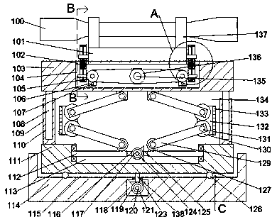
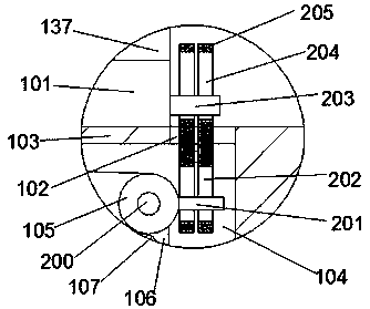
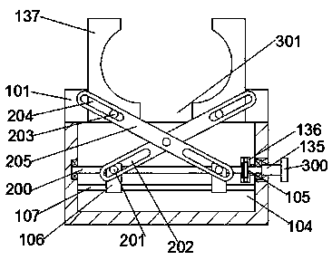
[0016] Combine below Figure 1-4 The present invention will be described in detail.

[0017] refer to Figure 1-4 According to an embodiment of the present invention, a sight directional positioning fastener includes a box body 114, an open cavity 115 is fixed inside the box body 114, and an inner cavity 118 is fixed inside the lower end wall of the open cavity 115, so The rear end wall of the inner cavity 118 is rotatably provided with a connecting rod 121 , the connecting rod 121 runs through the inner cavity 118 rotatably, and the outer surface of the connecting rod 121 is fixed with a power bevel gear 119 located in the inner cavity 118 And the angle handle 120 located in the external space, the rotating shaft 138 is set through the upper end wall of the inner cavity 118, and the outer surface of the rotating shaft 138 is fixed in the inner cavity 118 and meshed with the power bevel gear 119 The driven bevel gear 123 and the rotary block 111 located in the open cavity 11...


PUM


Abstract

The invention discloses a directional positioning fastener of a sight lens. The directional positioning fastener comprises a box, an opening cavity is fixedly arranged in the box, an inner cavity is fixedly arranged in the lower endwall of the opening cavity, a connecting rod is rotatably arranged onto the rear endwall of the inner cavity and rotatably penetrates the inner cavity, a power bevel gear located in the inner cavity and an angle handle located in the outer space are fixedly arranged on the outer surface of the connecting rod, a rotating shaft is rotatably and penetratingly arrangedonto the upper endwall of the inner cavity, a driven bevel gear located in the inner cavity and meshed with the power bevel gear and a rotary block located in the opening cavity are fixedly arranged on the outer surface of the rotating shaft, and balls are fixedly arranged on the lower endwall of the opening cavity. The directional positioning fastener is simple in structure and convenient to use,flexible angle adjustment of the sighting lens is realized by adopting an adjustable working mode, the working scope of the slighting lens is increased, working efficiency and quality of the slight lens are improved, and reliability of the equipment is improved.

Description

technical field [0001] The invention relates to the field of scopes, in particular to a scope orientation and positioning fastener. Background technique [0002] As a commonly used aiming tool for shooters, scopes are usually mounted on the gun body through matching fasteners or brackets. When aiming and shooting, it is usually necessary to adjust the shooting angle, distance, etc., while traditional fasteners Usually it only has the function of connecting the scope and the gun body. The shooter needs to aim by changing the position of the gun body. However, this kind of aiming is rough and cannot accurately capture the target. Shooting level, this device effectively solves such problems. Contents of the invention [0003] The object of the present invention is to provide a sight directional positioning fastener for overcoming the above-mentioned defects in the prior art. [0004] A fastening device for directional positioning of a scope according to the present inventio...

Claims


Application Information

Patent Timeline
IPC IPC(8): F41G1/16
CPCF41G1/16
Inventor 詹贺钫
Owner 詹贺钫
Learn More