A video monitoring method, device, terminal and computer storage medium

A video monitoring and sub-terminal technology, applied in computer components, computing, TV, etc., can solve the problem of not having too much energy to understand the status of students attending classes, lack of communication and communication between teachers and classmates, and not knowing the degree of students' mastery of knowledge points And other issues

Inactive Publication Date: 2020-01-14
房梦琦
View PDF10 Cites 0 Cited by
  • Summary
  • Abstract
  • Description
  • Claims
  • Application Information

AI Technical Summary

Problems solved by technology

However, under the current teaching method, students cannot communicate with the teacher in a timely manner on a knowledge point or question, resulting in a lack of communication and communication between the teacher and the students, and without the supervision of the teacher, only a small number of students can concentrate on In class, most students may ignore the teacher's concerns and knowledge points
Moreover, in the classroom, the teacher always teaches on it, and does not have too much energy to understand the status of each student, especially the students in the back seats. Therefore, most of the students are basically in an uncontrolled state, which makes the teacher do not understand. Students' mastery of knowledge points, and the overall grades of the final class are not ideal

Method used


Image

  • A video monitoring method, device, terminal and computer storage medium
  • A video monitoring method, device, terminal and computer storage medium
  • A video monitoring method, device, terminal and computer storage medium

Examples


Embodiment 1

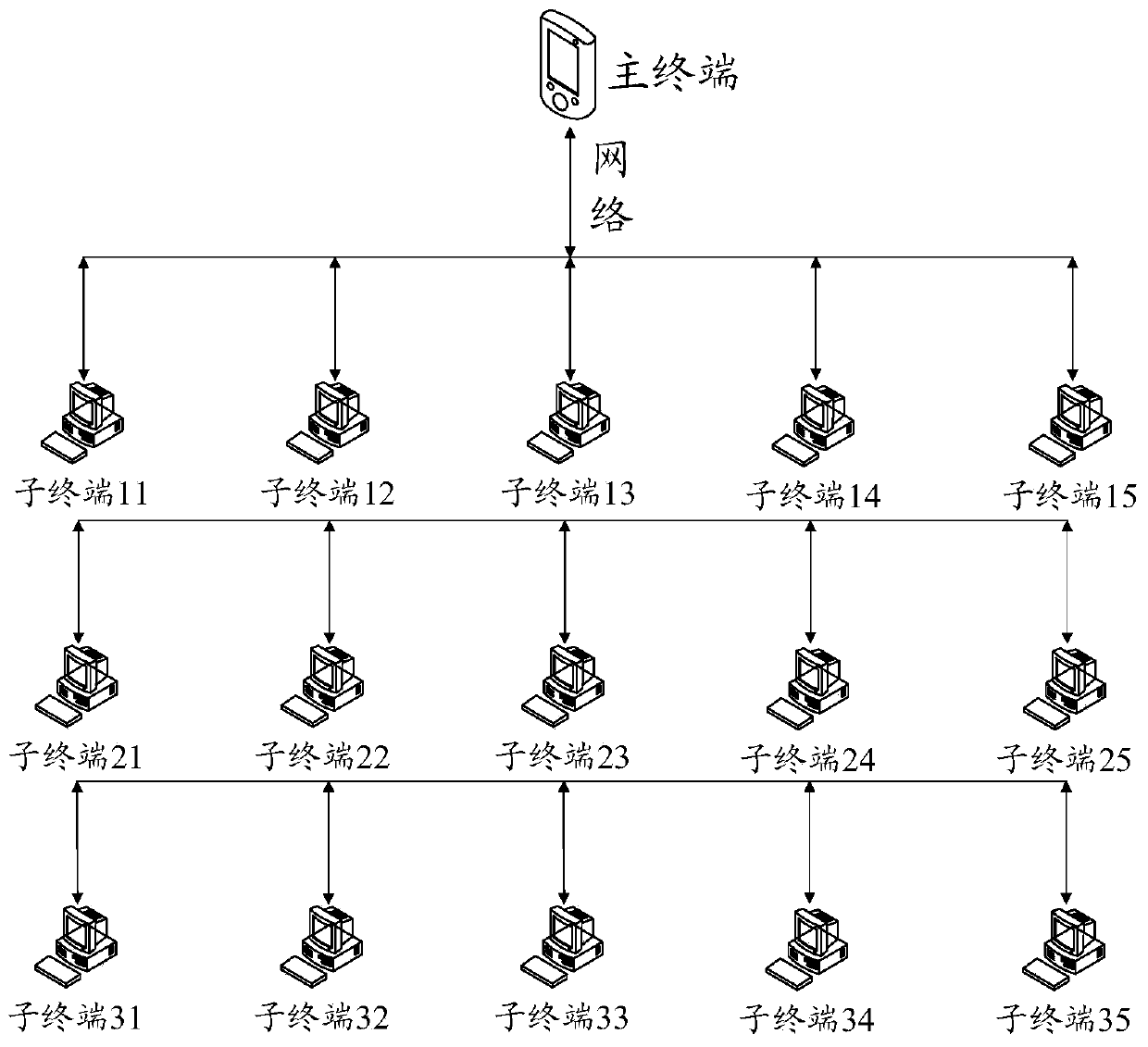
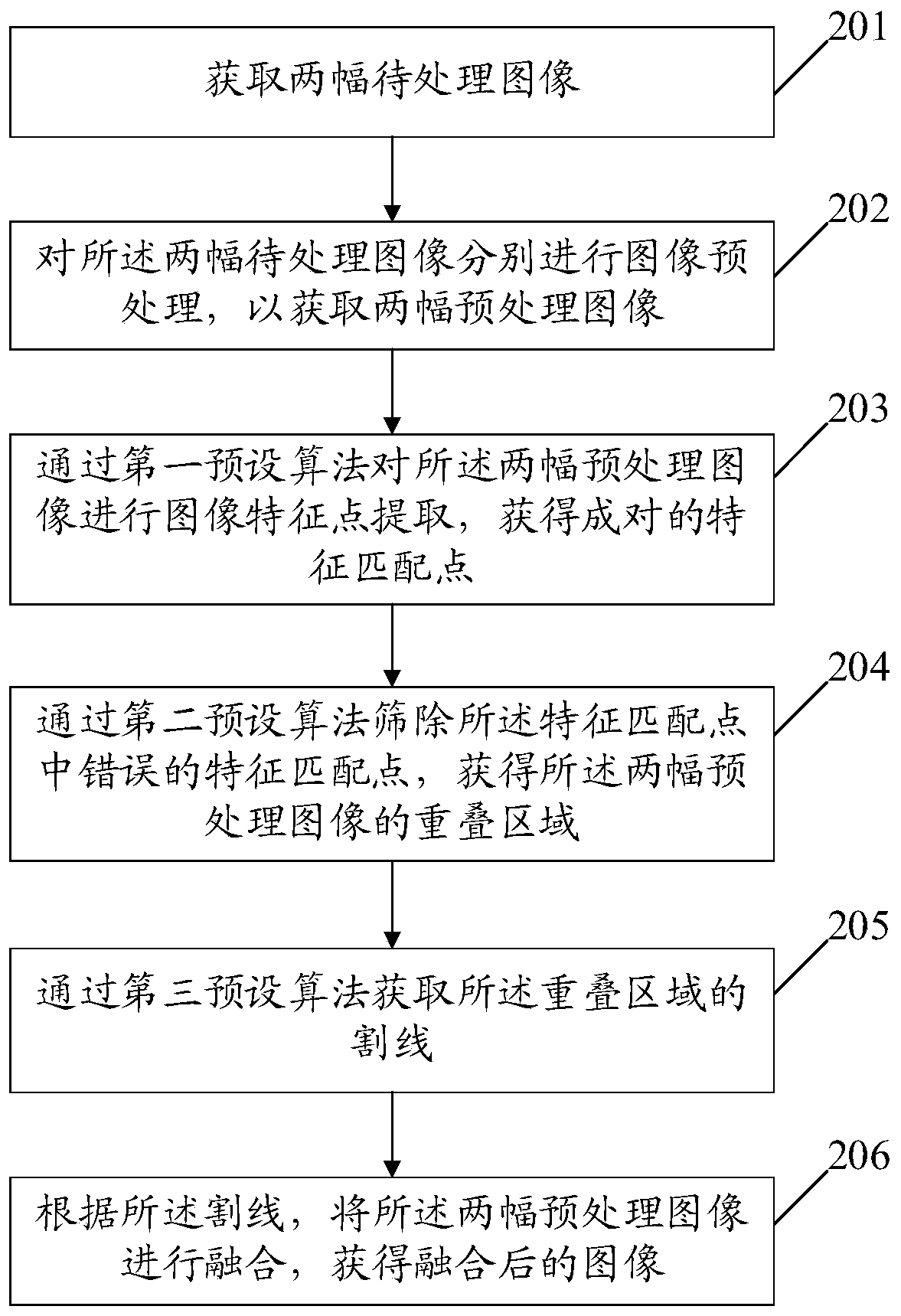
[0090] An embodiment of the present invention provides a video monitoring method, the method is applied to the main terminal, figure 2 A schematic diagram of a video monitoring method provided by an embodiment of the present invention, such as figure 2 As shown, the method mainly includes the following steps:

[0091] Step 201, acquiring two images to be processed;

[0092] Step 202, perform image preprocessing on the two images to be processed respectively, so as to obtain two preprocessed images;

[0093] Step 203, extracting image feature points from the two pre-processed images by using a first preset algorithm to obtain paired feature matching points;

[0094] Step 204, using a second preset algorithm to filter out the wrong feature matching points among the feature matching points, and obtain the overlapping area of ​​the two pre-processed images;

[0095] Step 205, obtain the secant line of the overlapping area through a third preset algorithm;

[0096] Step 206 ,...

Embodiment 2

[0131] An embodiment of the present invention provides a video monitoring method, the method is applied to a sub-terminal, Figure 5 A schematic diagram of a video monitoring method provided by an embodiment of the present invention, such as Figure 5 As shown, the method mainly includes the following steps:

[0132] Step 501, initialize the network socket of the sub-terminal, and send a connection request to the main terminal;

[0133] Step 502, sending a takeover message to the main terminal; wherein, the takeover message is used to instruct the main terminal to take over the sub-terminal;

[0134] Step 503, receiving the data packet sent by the master terminal;

[0135] Step 504, analyze the data packet to obtain the data packet type; wherein, the data packet type includes an interface device event;

[0136] Step 505: According to the data packet type, perform an interface device operation corresponding to the data packet type.

[0137] pass Figure 5 In the technical ...

Embodiment 3

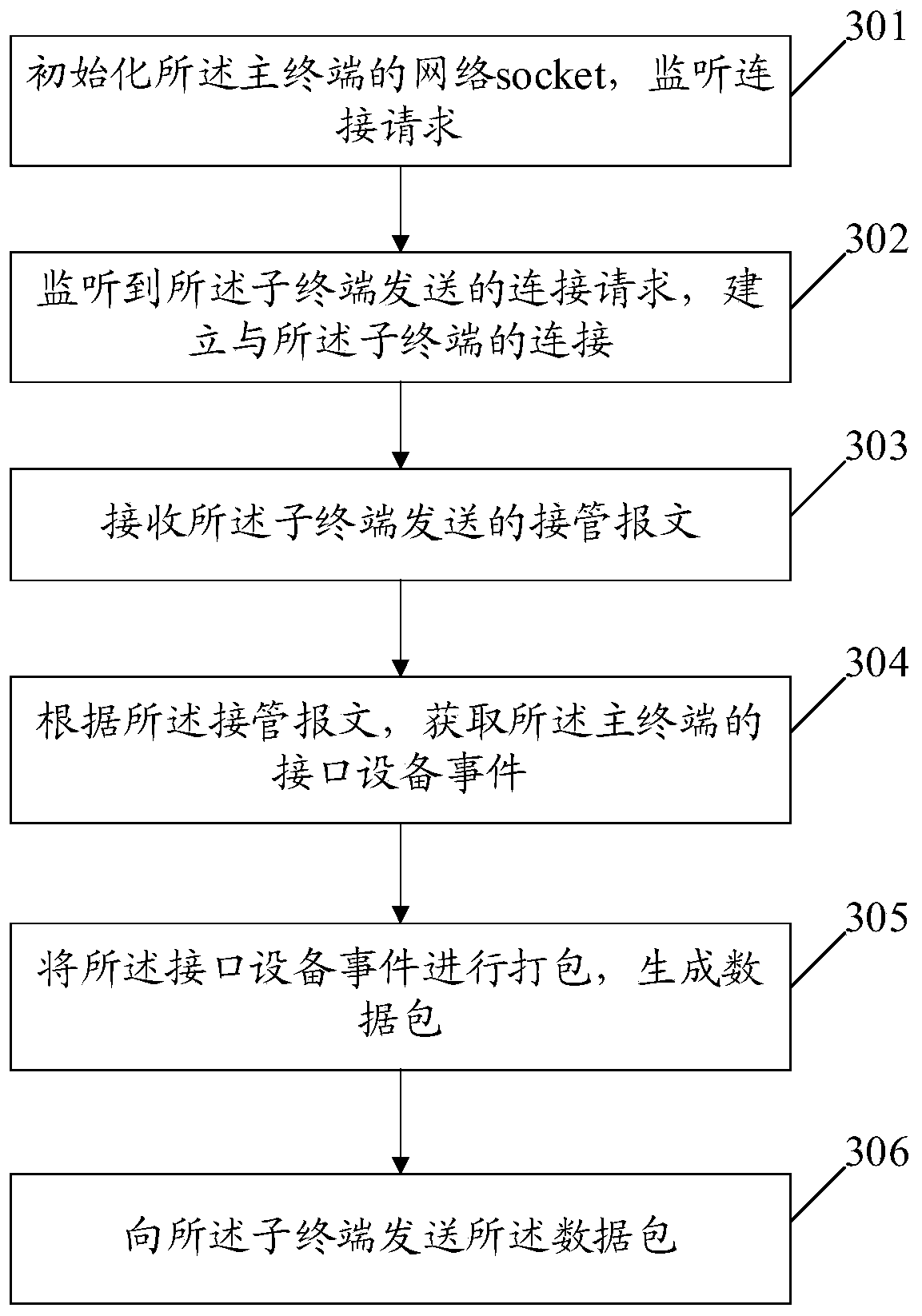
[0141] An embodiment of the present invention provides a video monitoring method, Figure 7 A schematic diagram of a video monitoring method provided by an embodiment of the present invention, such as Figure 7 As shown, the method mainly includes the following steps:

[0142] Step 701, the main terminal initializes the network socket of the main terminal, and monitors connection requests.

[0143] Here, the main terminal can monitor the connection request by initializing the local network socket socket. The main terminal initializes the local network socket by creating a socket and binding the socket to the main terminal's IP and listening port, so that the main terminal can Listen for requests sent by other terminals.

[0144] Step 702, the sub-terminal initializes the network socket of the sub-terminal, and sends a connection request to the main terminal.

[0145] It should be noted that the sub-terminal can send a connection request to the main terminal by initializing ...


PUM


Abstract

The embodiment of the present invention discloses a video monitoring method, equipment, terminal and computer storage medium. The method includes: acquiring two images to be processed; performing image preprocessing on the two images to be processed respectively to obtain two Preprocessing the image; extracting the image feature points of the two preprocessing images through a first preset algorithm to obtain paired feature matching points; filtering out the wrong feature matching in the feature matching points through a second preset algorithm point, to obtain the overlapping area of ​​the two pre-processed images; obtain the secant of the overlapping area through a third preset algorithm; according to the secant, fuse the two pre-processed images to obtain the fused image. In this way, real-time video stitching can be achieved by splicing the video sequences shot by the terminal and solving the problem of splicing traces in the spliced ​​images. It can also control the interface devices of the sub-terminals to facilitate communication between users.

Description

technical field [0001] The invention relates to the field of computer video teaching monitoring, in particular to a video monitoring method, equipment, terminal and computer storage medium. Background technique [0002] In recent years, with the rapid development of computer technology and the popularization of network technology, many technical teaching methods have emerged, for example, the current teaching methods such as electronic classrooms, distance learning, and multimedia. The teaching method of using computer technology to realize teaching has gradually attracted people's attention, so using computer technology to improve education is an inevitable trend in the development of education and teaching in today's era. However, under the current teaching method, students cannot communicate with the teacher in a timely manner on a knowledge point or question, resulting in a lack of communication and communication between the teacher and the students, and without the supe...

Claims


Application Information

Patent Timeline
Patent Type & Authority Patents(China)
IPC IPC(8): H04N7/18H04N5/265H04N5/232G06T3/40G06T5/50G06K9/46H04L29/06H04L29/08
CPCH04L67/141H04L69/162H04N5/265H04N7/181G06T3/4038G06T5/50G06T2207/10016G06T2207/20221G06V10/462H04N23/951
Inventor 房梦琦
Owner 房梦琦
Why Eureka
Try Eureka