Automobile pedal stroke test device

A technology for testing devices and automobile pedals, which can be applied to measuring devices, instruments, etc., can solve the problems of large space required, large errors, and complicated operation.

Active Publication Date: 2019-01-01
CHANGCHUN YIDONG CLUTCH
View PDF14 Cites 3 Cited by
  • Summary
  • Abstract
  • Description
  • Claims
  • Application Information

AI Technical Summary

Problems solved by technology

[0003] Existing domestic and international detection automobile pedal stroke technology has the use of pulleys, the number of turns required to measure the number of pulley turns, the number of turns sensor, and the backguy to measure the pedal stroke; The pulley frame measures the pedal stroke; however, the automobile pedal performance test device in the prior art has the disadvantages of low measurement accuracy, large error, complicated installation, and cumbersome operation.
[0004] In the current detection technology of automobile pedal stroke at home and abroad, there is also a wire-type displacement meter that needs a special fixture to measure the pedal stroke. However, the installation of this technical fixture will damage the test vehicle to a certain extent, and the space required is large, which is harmful to the testers. Disadvantages such as high technical requirements

Method used


Image

  • Automobile pedal stroke test device
  • Automobile pedal stroke test device
  • Automobile pedal stroke test device

Examples


Embodiment Construction

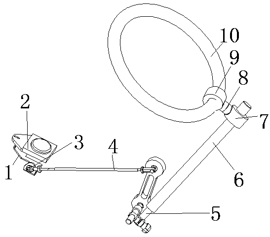
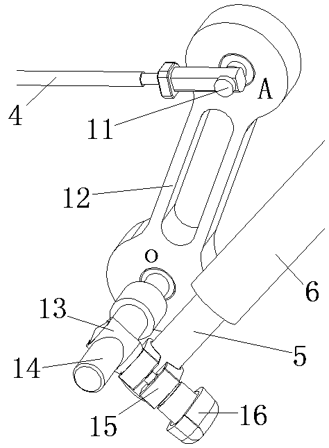
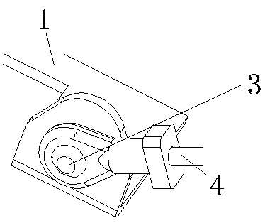
[0028] The present invention has a handlebar fixing sleeve 9 fitted on the handlebar 10, the handlebar fixing sleeve 9 is connected with the handlebar end hoop 7 through a lockable universal connector 8, and the handlebar end hoop 7 is set on an adjustable On the outer sleeve 6 of the support rod, the inner telescopic rod 5 of the length-adjustable support rod is inserted in the outer sleeve 6; The edge is fastened by fastening bolts 16, and a fixed sleeve 13 is fixedly installed on the outside of a folded edge. The fixed sleeve 13 is fixedly sleeved on the circular central shaft 14, and one end of the swing rod 12 is connected to the circular central shaft 14, and the other end of the swing rod 12 is connected to the circular central shaft 14. Swing shaft 11 shafts are connected, and one end of length-fixed support rod 4 is shaft-connected at the extension of swing shaft 11, and the other end of length-fixed support rod 4 is connected on the pedal 1 by pedal shaft 3 shafts.

...


PUM


Abstract

The invention relates to an automobile pedal stroke test device and belongs to the automobile performance detection device field. According to the automobile pedal stroke test device of the invention,the performance of an automobile pedal is tested with a steering wheel positioned. The automobile pedal stroke test device is provided with a steering wheel fixing sleeve which sleeves the steering wheel; the steering wheel fixing sleeve is connected with a steering wheel end hoop through a lockable universal connector; the steering wheel end hoop sleeves an outer sleeve; an inner telescopic rodis inserted into the outer sleeve; an end portion of the inner telescopic rod is sleeved with a clamping hoop; two folded edges of the clamping hoop are fastened through fastening bolts; the externalside of one of the folded edges is fixedly provided with a fixing sleeve; the fixing sleeve fixedly sleeves a center shaft; one end of a swing rod is in shafted connection with the center shaft; the other end of the swing rod is in shafted connection with a swing shaft; the extension portion of the swing shaft is in shafted connection with one end of a length fixed supporting rod; and the other end of the length fixed supporting rod is in shafted connection with the pedal through a pedal shaft. With the automobile pedal stroke test device of the invention adopted, the disadvantages of low measurement precision, large error, complicated installation, cumbersome operation, large required space, complicated operation, certain damage to a test vehicle caused by installation, and high technicalrequirements for testers can be eliminated.

Description

technical field [0001] The invention belongs to the field of automobile performance detection devices. Background technique [0002] The car pedal is one of the important parts for manipulating the car, and it can only be used if it meets a large number of performance tests. Among them, the pedal force and pedal travel are important indicators for evaluating the car's handling performance. [0003] Existing domestic and international detection automobile pedal stroke technology has the use of pulleys, the number of turns required to measure the number of pulley turns, the number of turns sensor, and the backguy to measure the pedal stroke; The pulley frame measures the pedal stroke; however, the automobile pedal performance test device in the prior art has the disadvantages of low measurement accuracy, large error, complicated installation, and cumbersome operation. [0004] In the existing domestic and foreign technologies for detecting the stroke of automobile pedals, the...

Claims


Application Information

Patent Timeline
Patent Type & Authority Applications(China)
IPC IPC(8): G01B21/02
CPCG01B21/02Y02T10/40
Inventor 王磊侯立世刘晓东齐帅侯宁
Owner CHANGCHUN YIDONG CLUTCH
Why Eureka
Try Eureka