Thin-wall microcellular foaming material and preparation facility thereof

A micro-foaming, thin-walled technology, applied in metal processing and other directions, can solve the problems of low processing efficiency of micro-foaming materials, single drilling function, cumbersome operation steps, etc., to increase the flexibility of rotation, and the clamping work is simple and convenient , the effect of improving work efficiency

Inactive Publication Date: 2019-01-04
泉州市披风熊科技有限公司
View PDF0 Cites 2 Cited by
  • Summary
  • Abstract
  • Description
  • Claims
  • Application Information

AI Technical Summary

Problems solved by technology

[0002] At present, when preparing and processing micro-foamed materials, drilling work is required. The current drilling equipment usually only has a single drilling function, so that it is necessary to repeat multiple drilling operations when drilling. For micro-foaming The processing efficiency of foam materials is low, and during processing, when clamping micro-foam materials, manual adjustment is required, and the operation steps are cumbersome and need to be improved

Method used


Image

  • Thin-wall microcellular foaming material and preparation facility thereof
  • Thin-wall microcellular foaming material and preparation facility thereof

Examples


Embodiment Construction

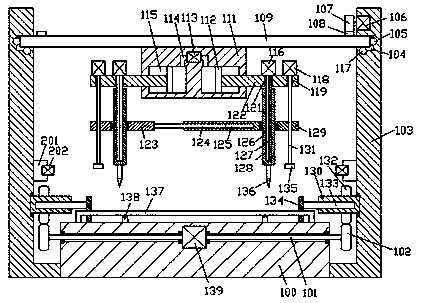
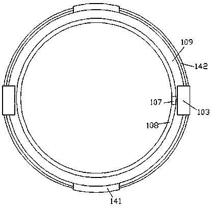
[0017] Combine below Figure 1-2 The present invention will be described in detail.

[0018] refer to Figure 1-2 , according to an embodiment of the present invention, a thin-walled micro-foamed material and its preparation facilities include a base 100 and support seats 103 symmetrically fixed on the left and right sides of the base 100, and the support seats on the left and right sides 103 is rotated and installed with an adapter plate 109, the bottom end surface of the adapter plate 109 is fixed with a processing frame 111, and the left and right symmetrical air pressure chambers 115 are arranged in the processing frame 111, and the air pressure chamber 115 is slidingly fitted. There is a piston plate 112, and the end faces of the opposite sides of the piston plates 112 on the left and right sides are fixed with a blending frame 122, and the blending frame 112 protrudes from the outer end of the processing frame 111 and is slidably connected with it. The top wall of the ...


PUM


Abstract

The invention discloses a thin-wall microcellular foaming material and a preparation facility thereof. The preparation facility comprises a base and supporting seats fixedly arranged on the left and right sides of the base in a bilateral symmetry mode. A rotary connecting disc is installed between the supporting seats on the left and right sides in a rotary fit mode. A machining frame is fixedly arranged on the bottom end face of the rotary connecting disc. Air pressure cavities are formed in the machining frame in a bilateral symmetry mode. Piston plates are installed in the air pressure cavities in a sliding fit mode. Adjusting frames are fixedly arranged on the end faces of the opposite sides of the piston plates on the left and right sides. The adjusting frames stretch out of the outerside end of the machining frame and are connected with the machining frame in a sliding fit mode. The top walls of the air pressure cavities are provided with air pressure holes in a communicating mode. The air pressure holes in the left and right sides are connected with air pressure cylinders. The air pressure cylinders are fixedly arranged in the machining frame. The parts, stretching out of the outer side end of the machining frame, of the adjusting frames are provided with first penetrating cavities in a vertical penetrated mode. Spline shafts are installed in the first penetrating cavities in a clearance fit mode.

Description

technical field [0001] The invention relates to the technical field of micro-foaming material processing, in particular to a thin-walled micro-foaming material and preparation facilities thereof. Background technique [0002] At present, when preparing and processing micro-foamed materials, drilling work is required. The current drilling equipment usually only has a single drilling function, so that it is necessary to repeat multiple drilling operations when drilling. For micro-foaming The processing efficiency of the foam material is low, and during processing, when the micro-foam material is clamped, manual adjustment is required, and the operation steps are cumbersome and need to be improved. Contents of the invention [0003] The object of the present invention is to provide a thin-walled micro-foaming material and its preparation facilities, which are used to overcome the above-mentioned defects in the prior art. [0004] According to the present invention, a thin-wa...

Claims


Application Information

Patent Timeline
IPC IPC(8): B26F1/16B26D7/00B26D7/02B26D7/26B26D5/08B26D5/02
CPCB26F1/16B26D5/02B26D5/08B26D7/00B26D7/02B26D7/2628
Inventor 曾强盛
Owner 泉州市披风熊科技有限公司
Why Eureka
Try Eureka