
Novel non-flash foaming mold structure and forming method thereof

A technology of foaming mold and molding method, which is applied in the field of new-type non-flash foaming mold structure and its molding, which can solve problems such as product flashing, achieve good product appearance, and save labor costs

Active Publication Date: 2019-01-04
YANFENG ADIENT SEATING CO LTD
View PDF5 Cites 4 Cited by
  • Summary
  • Abstract
  • Description
  • Claims
  • Application Information

AI Technical Summary

Problems solved by technology

[0004] In order to solve the problem of flashing caused by the foaming mold in the prior art, the present invention aims to provide a new foaming mold structure without flashing and its molding method

Method used


Image

  • Novel non-flash foaming mold structure and forming method thereof
  • Novel non-flash foaming mold structure and forming method thereof
  • Novel non-flash foaming mold structure and forming method thereof

Examples


Embodiment 1

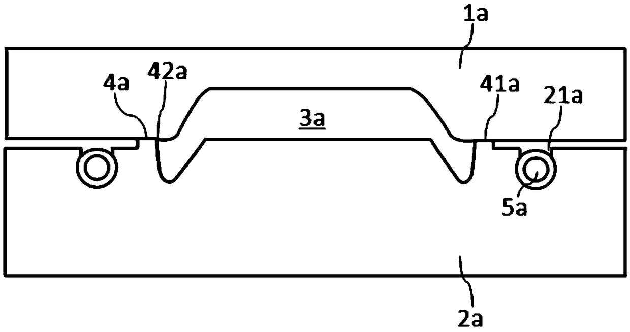
[0028] Such as image 3 As shown, according to a preferred embodiment of the present invention, the novel non-flash foaming mold structure comprises an upper mold 1a and a lower mold 2a, and the upper mold 1a and the lower mold 2a are closed to form a mold cavity 3a, and the upper mold 1a and the lower mold The opening and closing position of 2a has a contact surface 4a, the upper mold 1a and the lower mold 2a have a slit 41a at the position of the contact surface 4a, and the contact surface 4a has an adjoining seam 42a adjacent to the mold cavity 3a.

[0029] In this embodiment, the lower mold 2a has a groove 21a arranged around the mold cavity 3a, and the elastic body ring 5a as a deformation device is fixedly connected in the groove 21a. Such as Figure 4 As shown, the elastic body ring 5a is a circumferentially continuous soft material, which includes five elastic body sub-pieces 51a, and adjacent elastic body sub-pieces 51a are connected by connecting blocks 52a. In thi...

Embodiment 2

[0038] Such as Figure 6 As shown, according to a preferred embodiment of the present invention, the novel no-flash foaming mold structure includes an upper mold 1b and a lower mold 2b, and the upper mold 1b and the lower mold 2b are molded together to form a mold cavity 3b, and the upper mold 1b and the lower mold The opening and closing position of 2b has a contact surface 4b, the upper mold 1b and the lower mold 2b have a slit 41b at the position of the contact surface 4b, and the contact surface 4b has an adjoining seam 42b adjacent to the mold cavity 3b.

[0039] In this embodiment, the lower mold 2b has a first groove 21b disposed around the mold cavity 3b, and the elastic body ring 5b as a deformation device is fixedly connected in the first groove 21b. Such as Figure 7As shown, the elastic body ring 5b is a circumferentially continuous structure, which includes five elastic body sub-pieces 51b, and adjacent elastic body sub-pieces 51b are connected by connecting bloc...


PUM

PropertyMeasurementUnit
widthaaaaaaaaaa

Abstract

The invention relates to a novel non-flash foaming mold structure. An upper mold and a lower mold are assembled to form a mold cavity, the novel non-flash foaming mold structure is provided with a contact face on the separation-joint portion between the upper mold and the lower mold, and a slit is formed in the contact face between the upper mold and the lower mold; the novel non-flash foaming mold structure comprises a deformation device fixed on the upper mold or the lower mold, and the deformation device has a first state and a second state; under the first state, the deformation device isseparated from the lower mold or the upper mold so as to exhaust through the slit; under the second state, the deformation device is in contact with the lower mold or the upper mold and a sealing cavity is formed through the deformation device, and the sealing cavity is communicated with the mold cavity through the slit. The invention further provides a forming method of the novel non-flash foaming mold structure. A foaming product formed by the novel non-flash foaming mold structure is not provided with a flash and a hard edge, the product appearance is good, the later repairing step is omitted, and a large amount of labor cost is saved.

Description

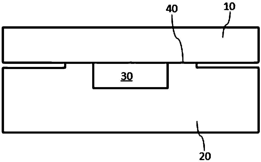
technical field [0001] The present invention relates to foaming, and more particularly relates to a novel non-flash foaming mold structure and a forming method thereof. Background technique [0002] Forming products by means of foam molds is a known process. The existing foaming mold includes an upper mold 10 and a lower mold 20, and the upper mold 10 and the lower mold 20 are molded together to form a mold cavity 30, and the foaming material is molded into a foamed product in the mold cavity 30. On the separation and closing position of the foaming mold, such as on the parting surface 40 of the upper mold 10 and the lower mold 20, although the upper mold 10 and the lower mold 20 will be matched by a sealant (such as red lead), the absolute ideal matching The position is easy to fail, and there is still a certain gap, which leads to foamed products often having flash, also known as overflow, burr, burr, etc. [0003] The flash on the molded product will affect the quality ...

Claims


Application Information

Patent Timeline
Patent Type & Authority Applications(China)
IPC IPC(8): B29C44/58B29C44/02
CPCB29C44/02B29C44/58B29C44/588
Inventor 黄红蕾严慧积张杨陈学春许伟贺云波马文辉于文辉蒋敏杰
Owner YANFENG ADIENT SEATING CO LTD
Learn More