Handle type door lock

A technology for handles and door locks, which is applied in the direction of wing leaf handles, wing leaf ball handles, building locks, etc., which can solve the problem that the lock hole is easy to be blocked, achieve easy hand-held operation, solve the problem that the lock hole is easy to be blocked, and improve friction force effect

Inactive Publication Date: 2019-01-04
泸州胡氏兴福智能科技有限公司
View PDF0 Cites 1 Cited by
  • Summary
  • Abstract
  • Description
  • Claims
  • Application Information

AI Technical Summary

Problems solved by technology

[0005] The purpose of the present invention is to provide a handle-type door lock

Method used


Image

  • Handle type door lock
  • Handle type door lock
  • Handle type door lock

Examples


Example Embodiment

[0028] Example 1:

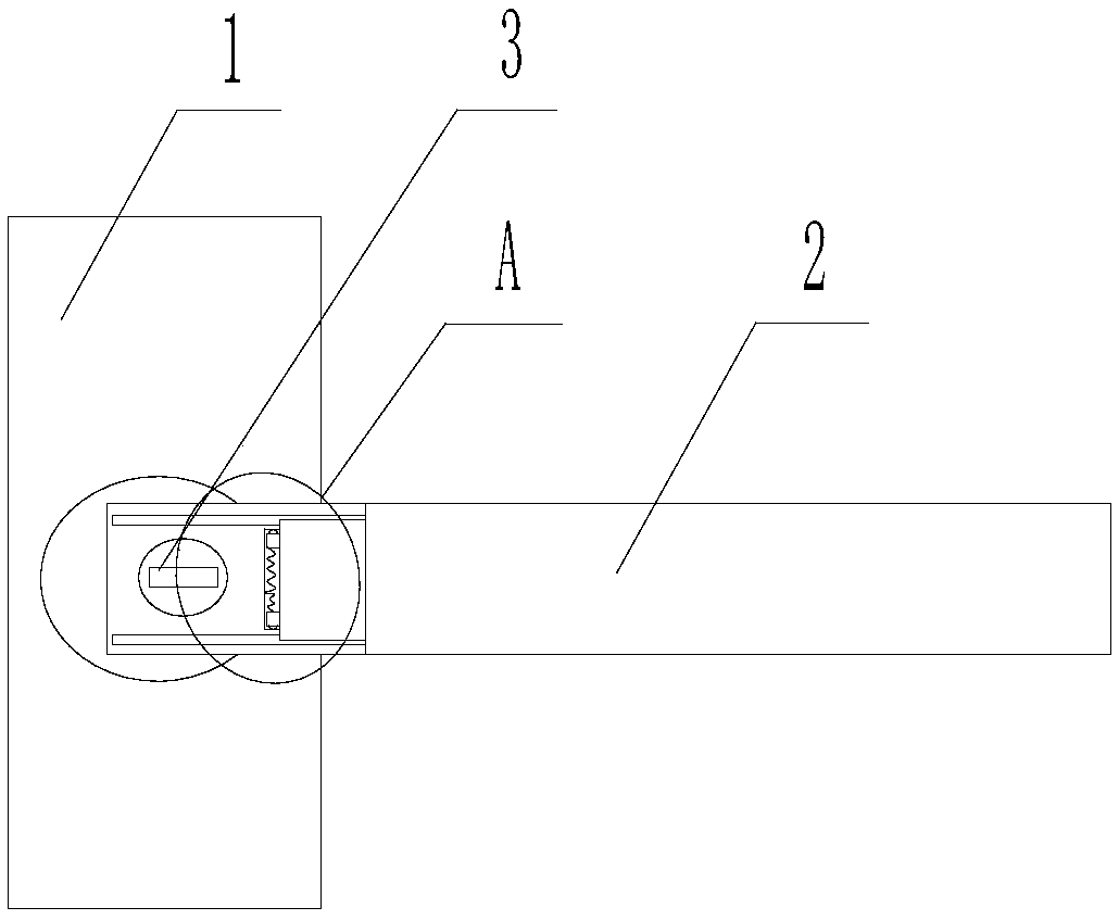
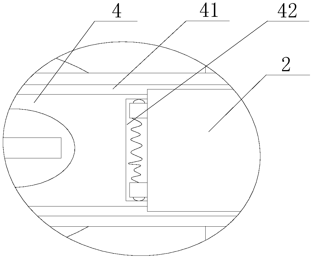
[0029] Such as Figure 1 to Figure 4 As shown, a handle-type door lock includes a lock shell 1, a handle 2 is provided on the lock shell 1, and a lock hole 3 is provided on the upper end of the handle 2, and the lock hole 3 is provided between the handle 2 and the lock One end of the shell 1 is connected, one end of the handle 2 sinks to form a stepped structure, the lower end of the stepped structure is the mounting surface 4, and the higher end is the hand-held surface. The connection between the mounting surface 4 and the hand-held surface is provided On the vertical surface, the lock hole 3 is provided on the mounting surface 4, the vertical surface is provided with a U-shaped limiting groove 21, a U-shaped cover plate is provided in the U-shaped limiting groove, and the mounting surface 4 Two sliding grooves 41 matched with the U-shaped cover plate are symmetrically provided on the upper side. The sliding grooves 41 are connected to both sides of the U-s...

Example Embodiment

[0030] Example 2:

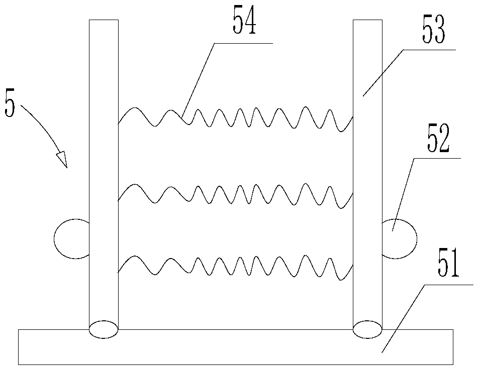
[0031] Such as Figure 1 to Figure 4 As shown, this embodiment is based on Embodiment 1, the limiting block 52 is a 3 / 4 spherical structure, and the limiting groove is a 3 / 4 spherical groove; the through groove 42 is provided at the rightmost end of the mounting surface 4 ; The hand-held surface is set as a rough surface.


PUM


Abstract

The invention discloses a handle type door lock. The handle type door lock comprises a lock housing, wherein a handle is arranged on the lock housing; a lock hole is formed in the upper end surface ofthe handle; one end of the handle is sunken to form a step structure; the lower end of the step structure is treated as a mounting surface, and the higher end of the step structure is treated as a handheld surface; a vertical surface is arranged at a part where the mounting surface is connected to the handheld surface; the lock hole is formed in the mounting surface; a U-shaped limiting groove isformed in the vertical surface, and a U-shaped cover plate is arranged in the U-shaped limiting groove; two chutes which fit the U-shaped cover plate are symmetrically formed in the mounting surface;a through groove in which a clamping mechanism is arranged is formed between the two chutes in the upper end surface of the mounting surface; the clamping mechanism comprises a fixing plate on whichtwo limiting rods are symmetrically hinged; the two limiting rods are connected through an elastic part; limiting blocks are arranged at the outer sides of the limiting rods; and limiting grooves which fit the limiting blocks are formed in the sidewall of the through groove. The handle type door lock solves the problem that a lock hole in an existing door lock is easily blocked.

Description

technical field [0001] The invention relates to the technical field of door locks, in particular to a handle-type door lock. Background technique [0002] Door lock, a structure added to objects such as doors, boxes, drawers, etc., can only be opened with a special key. There are many types of door locks, and the requirements for door locks are different in various occasions. Ordinary families generally use anti-theft door locks, which are highly secure and relatively cheap; in some high-end places, security agencies will use combination locks and fingerprint locks. Very high and expensive. [0003] At present, all the doors of every household are equipped with door locks, and the door locks are not only required to be anti-theft, but also required to be comfortable to use and not easily damaged. [0004] At present, household door locks pay more attention to anti-theft and comfort, but usually the lock hole is exposed, which easily leads to blockage of the lock hole, and ...

Claims


Application Information

Patent Timeline
IPC IPC(8): E05B17/18E05B1/00
CPCE05B17/186E05B1/00
Inventor 胡兴华
Owner 泸州胡氏兴福智能科技有限公司
Why Eureka
Try Eureka