A grooved series multi-stage pressure reducing regulating valve

A pressure-reducing regulating valve, grooved technology, applied in the direction of lift valve, valve details, valve device, etc., can solve problems such as movement jam, fluid short circuit, easy to block flow channel, etc., achieve high strength and shock resistance, eliminate Noise and vibration, flash suppression effect

Active Publication Date: 2020-04-24
HEFEI GENERAL MACHINERY RES INST +1
View PDF6 Cites 0 Cited by
  • Summary
  • Abstract
  • Description
  • Claims
  • Application Information

AI Technical Summary

Problems solved by technology

However, this type of parallel multi-stage decompression regulating valve also has the following problems: 1. The flow channel is relatively narrow, and solid particles are easy to block the flow channel, and at the same time, it is easy to enter between the valve core and the sleeve, causing motion jamming; 2. Small opening When the temperature is high, it is easy to cause a short circuit of the fluid due to the excessive size of the internal parts

Method used


Image

  • A grooved series multi-stage pressure reducing regulating valve
  • A grooved series multi-stage pressure reducing regulating valve
  • A grooved series multi-stage pressure reducing regulating valve

Examples


Embodiment 1

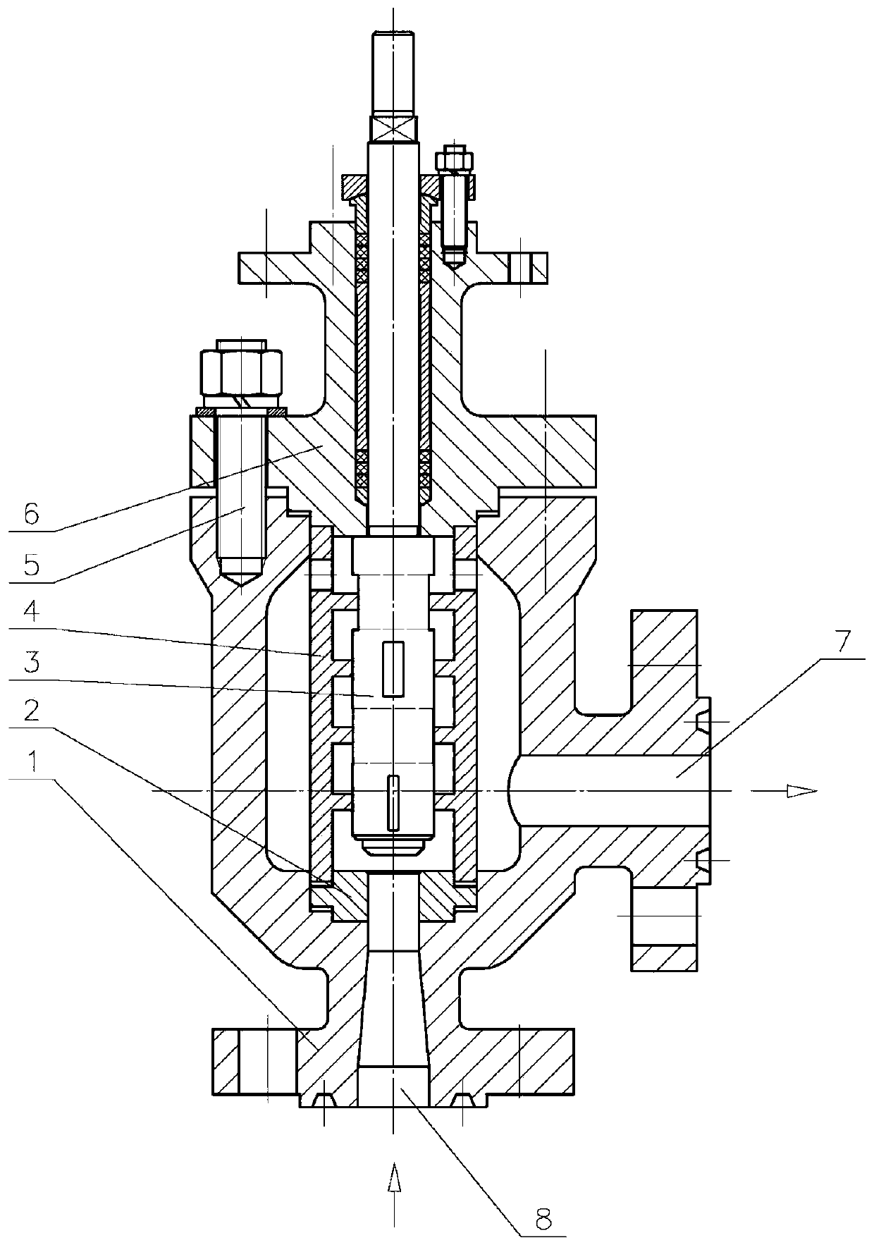
[0028] like figure 1 , 2 As shown, this specific embodiment is a grooved series multi-stage pressure reducing regulating valve, which is a series four-stage pressure reducing regulating valve, including a valve body 1, and a cavity formed by the valve body 1 and the valve cover 6 is provided with a pressure reducing valve. Energy chamber 4 and valve seat 2; through the middle flange fastening bolt 5 between the valve cover 6 and the valve body 1, the energy dissipation chamber 4 is tightly pressed between the valve cover 6 and the valve seat 2; the inner wall of the energy dissipation chamber 4 There are four-stage rib plates at equal intervals, and the end of the energy dissipation chamber 4 close to the valve cover 6 is provided with diversion holes 4e uniformly distributed in the circumferential direction; The grooved valve core 3 is slidably matched with the four-stage rib on the inner wall of the energy dissipation chamber 4 , and the rib precisely guides the grooved val...

Embodiment 2

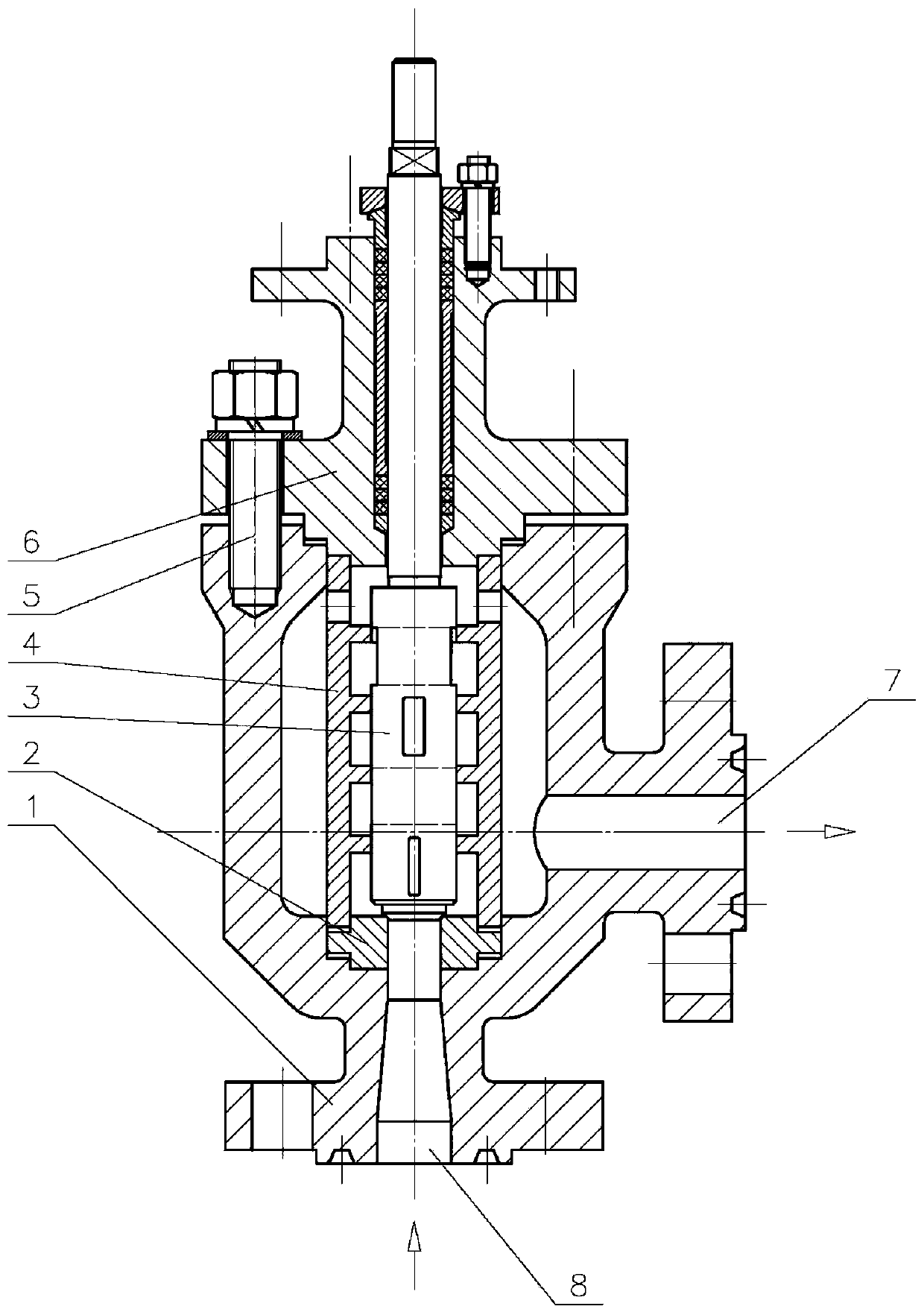
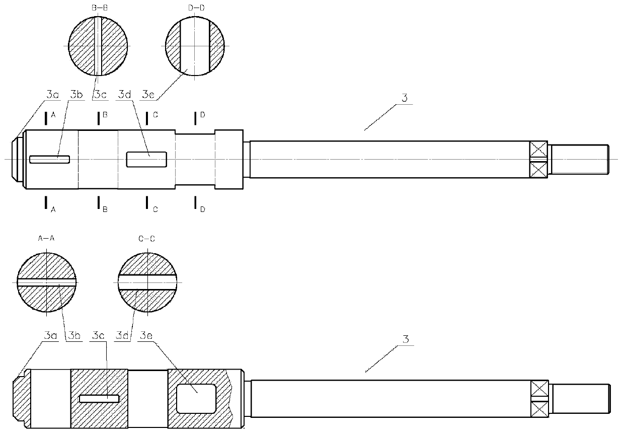
[0033] The difference between this embodiment and Embodiment 1 is that the decompression groove is non-penetrating; the structure diagram of the grooved series multi-stage decompression regulating valve in the fully open state, and the structure of the grooved series multistage decompression regulating valve in the closed state The schematic diagram and the schematic diagram of the grooved valve core structure are as follows Figure 4 , 5 , 6 shown.

[0034] The grooved series-connected multi-stage pressure-reducing regulating valves in Example 1 and Example 2 are all series-connected four-stage pressure-reducing regulating valves. Except for the four-stage pressure-reducing regulating valve, the grooved series-connected multi-stage pressure-reducing regulating valve in the present invention is The regulating valve can also be a two-stage, three-stage, five-stage and more than five-stage regulating valve.


PUM


Abstract

The invention relates to a grooving serial-connected multistage pressure reduction adjusting valve, and relates to the technical field of multistage pressure reduction adjusting valves. The grooving serial-connected multistage pressure reduction adjusting valve comprises a valve body and a valve cover; the valve body is provided with a valve inlet and a valve outlet; a valve base, a grooving valveelement capable of axially moving and an energy dissipating chamber are arranged in a cavity surrounded by the valve body and the valve cover; the energy dissipating chamber is tightly ejected between the valve base and the valve cover; a guide hole is formed in the end, near the valve cover, of the energy dissipating chamber; a multistage rib plate arranged on the inner wall of the energy dissipating chamber is matched and slidingly connected with the grooving valve element to form a multistage pressure reduction throttling unit; and the grooving valve element is axially provided with a pressure reducing groove corresponding to the rib plate. Through separate design of a throttling surface and a sealing surface, the scouring damage of high-speed medium currents to the sealing surface iseffectively prevented under the working condition of small openness; the multistage pressure reduction throttling unit is serially connected to effectively prevent the valve blockage caused by solid particles in mediums; and the multistage throttling area ratio is distributed to effectively inhibit the erosion damage to the grooving valve element and the energy dissipating chamber by flash evaporation and cavitation.

Description

technical field [0001] The invention relates to the technical field of multi-stage pressure reducing regulating valves, in particular to a grooved series multi-stage pressure reducing regulating valve. Background technique [0002] The control valve is an important part of automatic control, and its adjustment accuracy and reliability will affect the safety and stability of automatic operation. For the high pressure differential working conditions of gas, liquid, steam, solid-containing liquid and other media, the commonly used single-seat plunger type regulating valve or traditional single-stage sleeve type regulating valve has the disadvantage of short service life. The short service life is mainly due to the following two reasons: 1. Cavitation caused by flash evaporation and cavitation under high pressure differential conditions, and the burst of bubbles releases huge energy, which is easy to make grooved valve cores, valve seats, etc. Honeycomb-shaped pits are formed o...

Claims


Application Information

Patent Timeline
Patent Type & Authority Patents(China)
IPC IPC(8): F16K1/00F16K1/36F16K1/42F16K47/04F16K47/02
CPCF16K1/00F16K1/36F16K1/42F16K47/02F16K47/04
Inventor 王渭明友陈凤官耿圣陶余宏兵叶晓节郭怀舟吴怀昆高红彪郝伟沙
Owner HEFEI GENERAL MACHINERY RES INST
Why Eureka
Try Eureka