Adjusting device for display camera

A technology for adjusting devices and cameras, which is applied in the direction of supporting machines, mechanical equipment, machine platforms/supports, etc., and can solve problems such as inability to move, limited camera position, and inability to change the position of the display camera

Inactive Publication Date: 2019-01-04
ZHENGZHOU TIANSHUN ELECTRONICS TECH CO LTD
View PDF10 Cites 13 Cited by
  • Summary
  • Abstract
  • Description
  • Claims
  • Application Information

AI Technical Summary

Problems solved by technology

[0003] The current display camera is usually built in the top of the display. Since the position is fixed and cannot be moved, the image captured by the camera is only in front of the display, which cannot meet the needs of users.
[0004] In order to solve the problem that the position of the display camera cannot be changed, a Chinese patent (CN202306395U) discloses a fixing device for a special camera for a display. The device includes a camera and a clamping arm. On the frame of the display, and then tighten the screws to fasten it, but because the device is clamped on the frame of the display, the position of the camera is very limited, and it is difficult to meet the requirements of the user

Method used


Image

  • Adjusting device for display camera
  • Adjusting device for display camera
  • Adjusting device for display camera

Examples


Embodiment Construction

[0022] The technical solution of this patent will be further described in detail below in conjunction with specific embodiments.

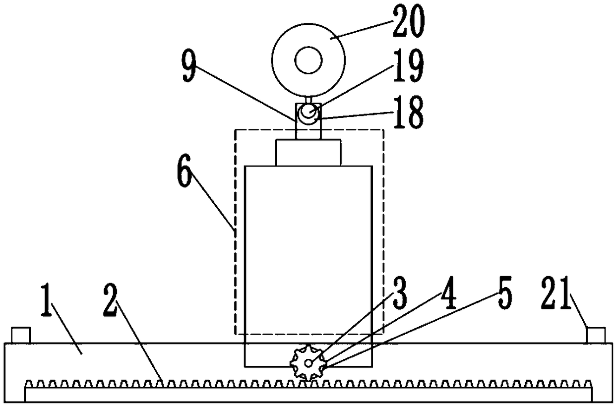
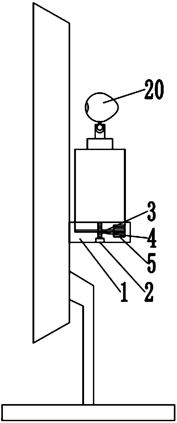
[0023] see figure 1 and image 3 , a display camera adjustment device, including a base 1, the two ends of the base 1 are provided with stoppers 21 to prevent the lifting device 6 from sliding to the edge position and falling off, the base 1 is provided with a rack 2, and a rotating shaft is provided above the rack 2 3. The rotating shaft 3 is fixedly connected with the gear 4, the first motor 5 is arranged behind the gear 4, the first motor 5 is fixedly connected to the side wall of the first cylinder 7, and the top of the third cylinder 9 is provided with a ball groove 18, A universal ball 19 is arranged in the ball groove 18, and a camera 20 is fixedly connected to the top of the universal ball 19, and the orientation and angle of the camera 20 can be adjusted by rotating the universal ball 19.

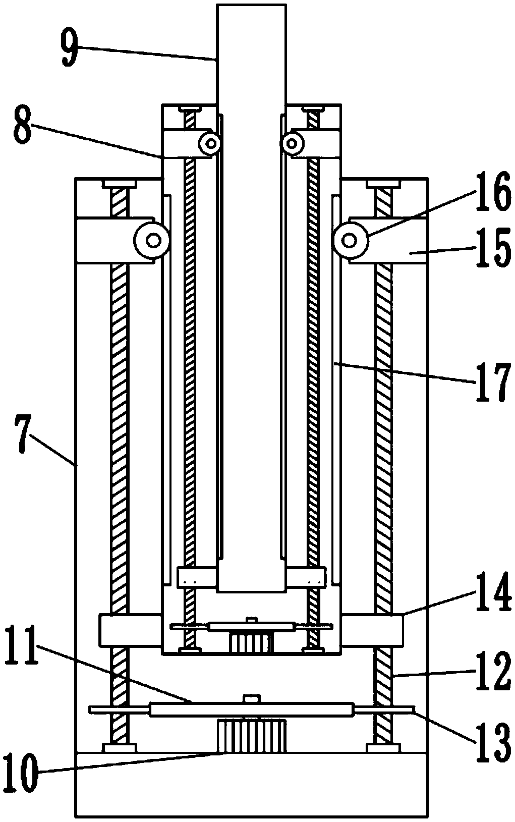
[0024] see figure 2 , a display camera adjust...


PUM


Abstract

The invention discloses an adjusting device for a display camera. The adjusting device for the display camera comprises a base, and a lifting device is slid ably connected to the upper portion of thebase. The lifting device comprises a first column body, a second column body and a third column body, wherein a second motor is fixedly connected to the bottoms of the first column body and the secondcolumn body, a big gear wheel is fixedly connected to the output shaft of the second motor, two screws are rotatable connected to the interiors of the first column body and the second column body, and pinions are fixedly connected to the lower portion of the screws. According to the adjusting device for the display camera, the lifting device slides on the base left and right, the position of thecamera can be adjusted in the horizontal direction; by the rotation of the second motor, under the action of gear drive and screw drive, the second column body and the third column body are controlledto be lifted and lowered, the position of the camera can be adjusted in the vertical direction; by rotation of a universal ball, the orientation and the angle of the camera can be adjusted, under thecommon adjusting action, the camera can be adjusted in any position within reasonable range, and the requirements of users are practically met.

Description

technical field [0001] The invention relates to an electronic device, in particular to a device for adjusting a display camera. Background technique [0002] Camera, also known as computer camera, computer eye, electronic eye, etc., is a video input device that is widely used in video conferencing, telemedicine and real-time monitoring. Ordinary people can also talk and communicate with each other through the network with images and sounds through the camera. In addition, people can also use it for various popular digital images, audio-visual processing, etc. [0003] The current display camera is usually built into the top of the display. Since the position is fixed and cannot be moved, the picture captured by the camera is only in front of the display, which cannot meet the needs of users. [0004] In order to solve the problem that the position of the display camera cannot be changed, a Chinese patent (CN202306395U) discloses a fixing device for a special camera for a d...

Claims


Application Information

Patent Timeline
Patent Type & Authority Applications(China)
IPC IPC(8): F16M11/04F16M11/14F16M11/18F16M11/24
CPCF16M11/045F16M11/14F16M11/18F16M11/2078F16M11/2085F16M11/242
Inventor 李欣
Owner ZHENGZHOU TIANSHUN ELECTRONICS TECH CO LTD
Why Eureka
Try Eureka