Light source for illumination and illuminating device
A technology of light source and light-emitting element, which is applied to lighting devices, lighting device parts, light sources, etc., can solve the problems of reduced LED light quantity, uneven emitted light, and reduced detection performance of human-sensing sensors, and achieves the goal of suppressing light disturbances. uniform effect
- Summary
- Abstract
- Description
- Claims
- Application Information
AI Technical Summary
Problems solved by technology
Method used
Image

Examples
Embodiment 1
[0041] [structure]
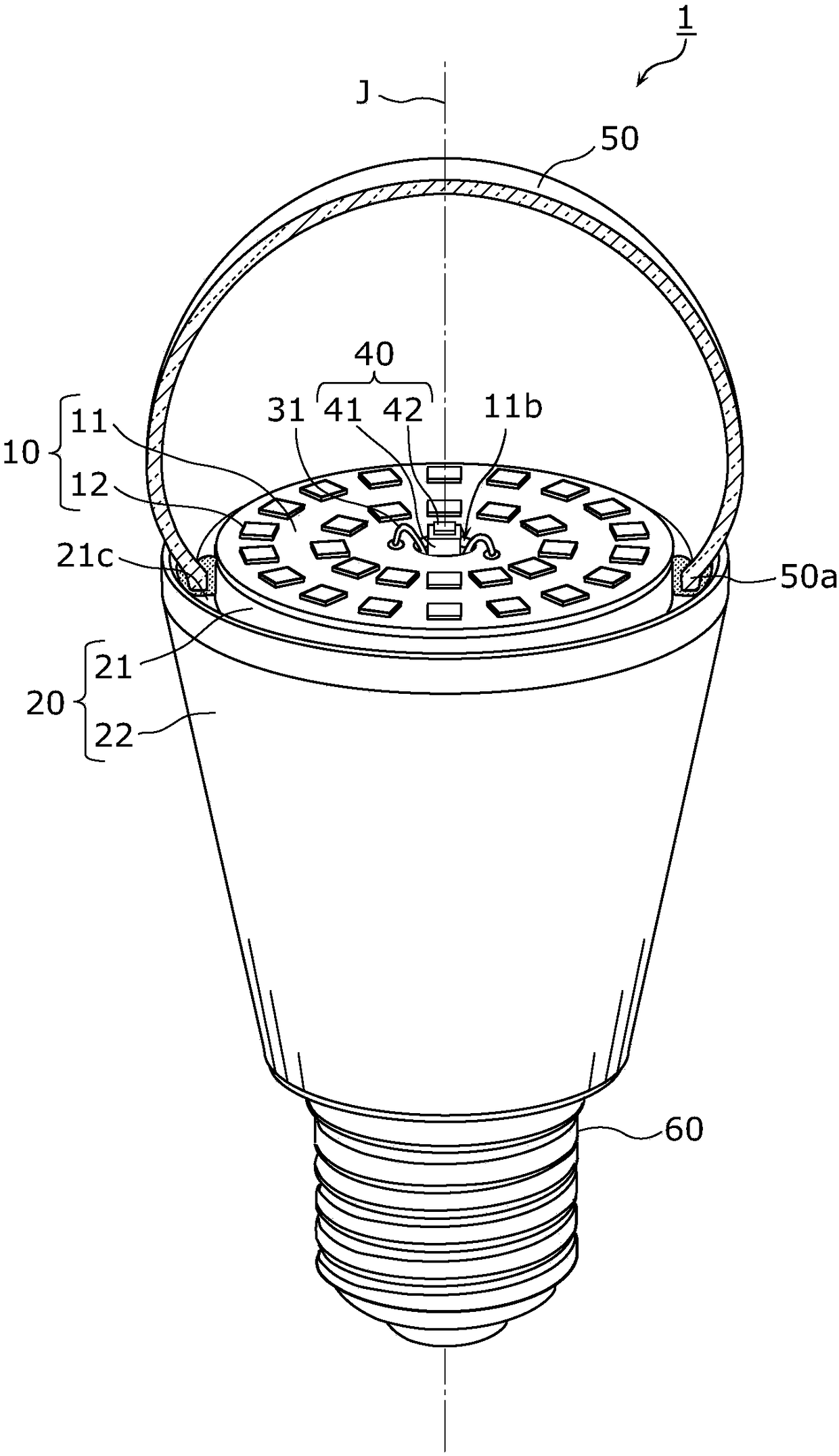
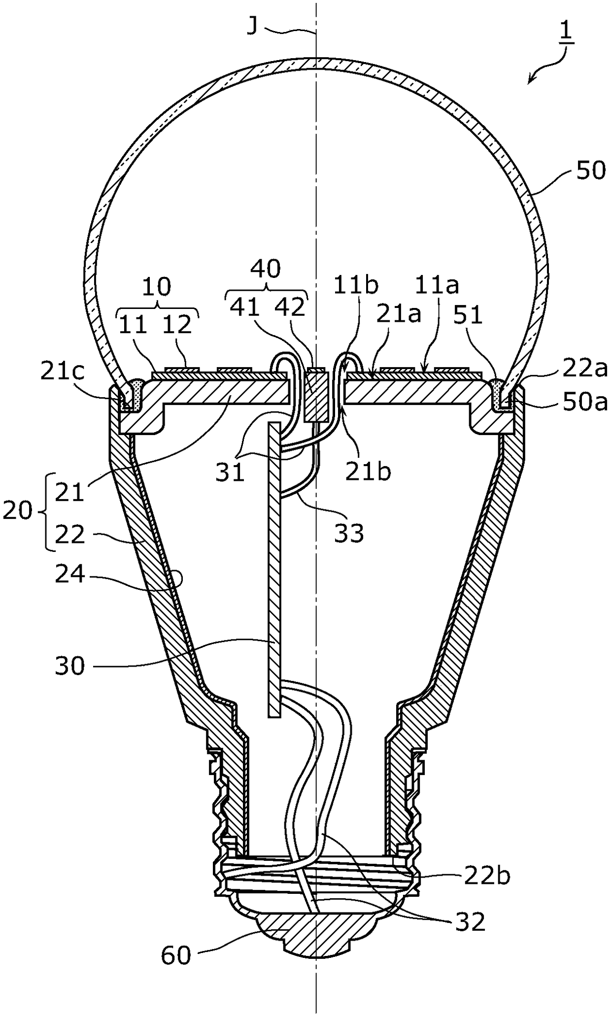
[0042] First, for the overall structure of the bulb-shaped lamp related to Example 1, use figure 1 as well as figure 2 Be explained.
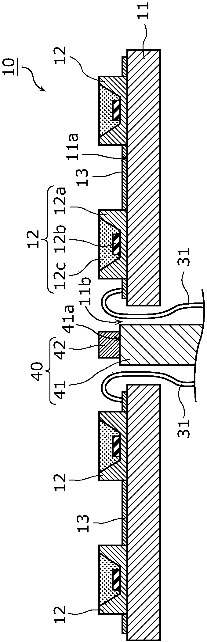
[0043] figure 1 It is a notched perspective view of a part of the LED lamp 1 according to this embodiment. figure 2 It is a sectional view of the LED lamp 1 concerning this Example. Moreover, in figure 1 In , in order to show the LED module 10 inside the glove 50, a part of the glove 50 is cut away and shown.
[0044] and, in figure 1 as well as figure 2 In , the dotted line drawn along the vertical direction of the drawing shows the lamp axis (central axis) J of the light bulb-shaped lamp 1 . In this embodiment, the lamp axis J coincides with the axis of the globe 50 (globe axis). Furthermore, the lamp axis J is an axis that becomes the center of rotation when the lightbulb-shaped lamp 1 is attached to the socket of the lighting device, and coincides with the rotation axis of the base 60 .
[0045] Such as fi...
Deformed example 1
[0125] Next, for Modification 1 of Embodiment 1, use Figure 5 as well as Figure 6 Be explained. Figure 5 It is a notched perspective view of a part of the light bulb-shaped lamp 101 which concerns on this modification. Figure 6 It is a sectional view showing the LED module 10 , the information obtaining module 40 , and the reflector 70 of the light bulb-shaped lamp 101 according to this modification.
[0126] Such as Figure 5 as well as Figure 6 As shown, the lightbulb-shaped lamp 101 differs from the lightbulb-shaped lamp 1 according to the first embodiment in that a reflector 70 is newly provided. Hereinafter, description will focus on differences from Embodiment 1, and description of common points will be omitted.
[0127] The reflector 70 is arranged around the information obtaining module 40 . In this modified example, the reflecting plate 70 is a cylindrical body whose axis is the penetration direction of the through hole 11b, and is also a cylindrical body w...
Deformed example 2
[0138] Next, for Modification 2 of Embodiment 1, use Figure 7 Be explained. Figure 7 It is a sectional view of the light bulb-shaped lamp 201 which concerns on this modification.
[0139] Such as Figure 7 As shown, the lightbulb-shaped lamp 201 differs from the lightbulb-shaped lamp 1 according to the first embodiment in that a resin cover 80 is newly provided. Hereinafter, description will focus on differences from Embodiment 1, and description of common points will be omitted.
[0140] Such as Figure 7 As shown, the resin cover 80 covers the information obtaining module 40 . Specifically, the resin cover 80 is a housing for accommodating the information obtaining module 40 , and has a through hole through which the lead wire 33 is pulled out.
[0141] The resin cover 80 is formed of, for example, an insulating resin material. Accordingly, insulation between the information obtaining module 40 and the LED module 10 can be ensured. The resin cover 80 may be formed o...
PUM
 Abstract
Description
Claims
Application Information
 - R&D
- Intellectual Property
- Life Sciences
- Materials
- Tech Scout
- Unparalleled Data Quality
- Higher Quality Content
- 60% Fewer Hallucinations
Browse by: Latest US Patents, China's latest patents, Technical Efficacy Thesaurus, Application Domain, Technology Topic, Popular Technical Reports.
© 2025 PatSnap. All rights reserved.Legal|Privacy policy|Modern Slavery Act Transparency Statement|Sitemap|About US| Contact US: help@patsnap.com