Vehicle head lamp

A technology for headlights and vehicles, which is applied in vehicle lighting systems, headlights, vehicle parts, etc., and can solve problems such as large-scale and complex lamps and lanterns.

Inactive Publication Date: 2004-11-03
KOITO MFG CO LTD
View PDF2 Cites 10 Cited by
  • Summary
  • Abstract
  • Description
  • Claims
  • Application Information

AI Technical Summary

Problems solved by technology

[0009] However, when the vehicle headlamp disclosed in "Patent Document 1" is used, there is a problem that the structure of the lamp is complicated and large.

Method used


Image

  • Vehicle head lamp
  • Vehicle head lamp
  • Vehicle head lamp

Examples


Embodiment Construction

[0044] Embodiments of the present invention will be described below with reference to the accompanying drawings.

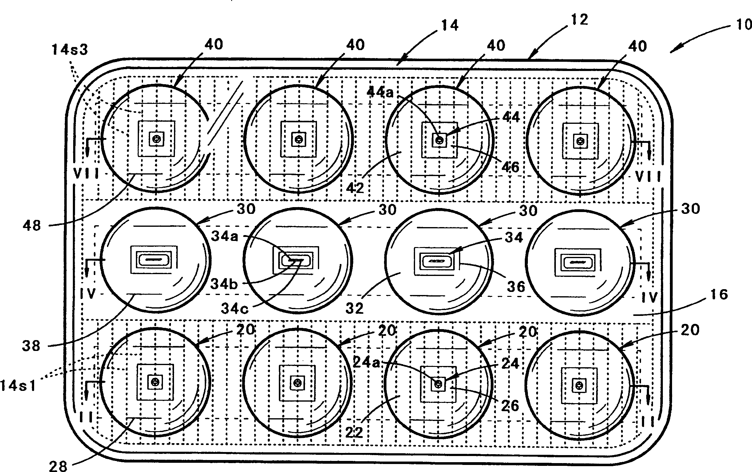
[0045] figure 1 A front view showing a vehicle headlamp according to an embodiment of the present invention.

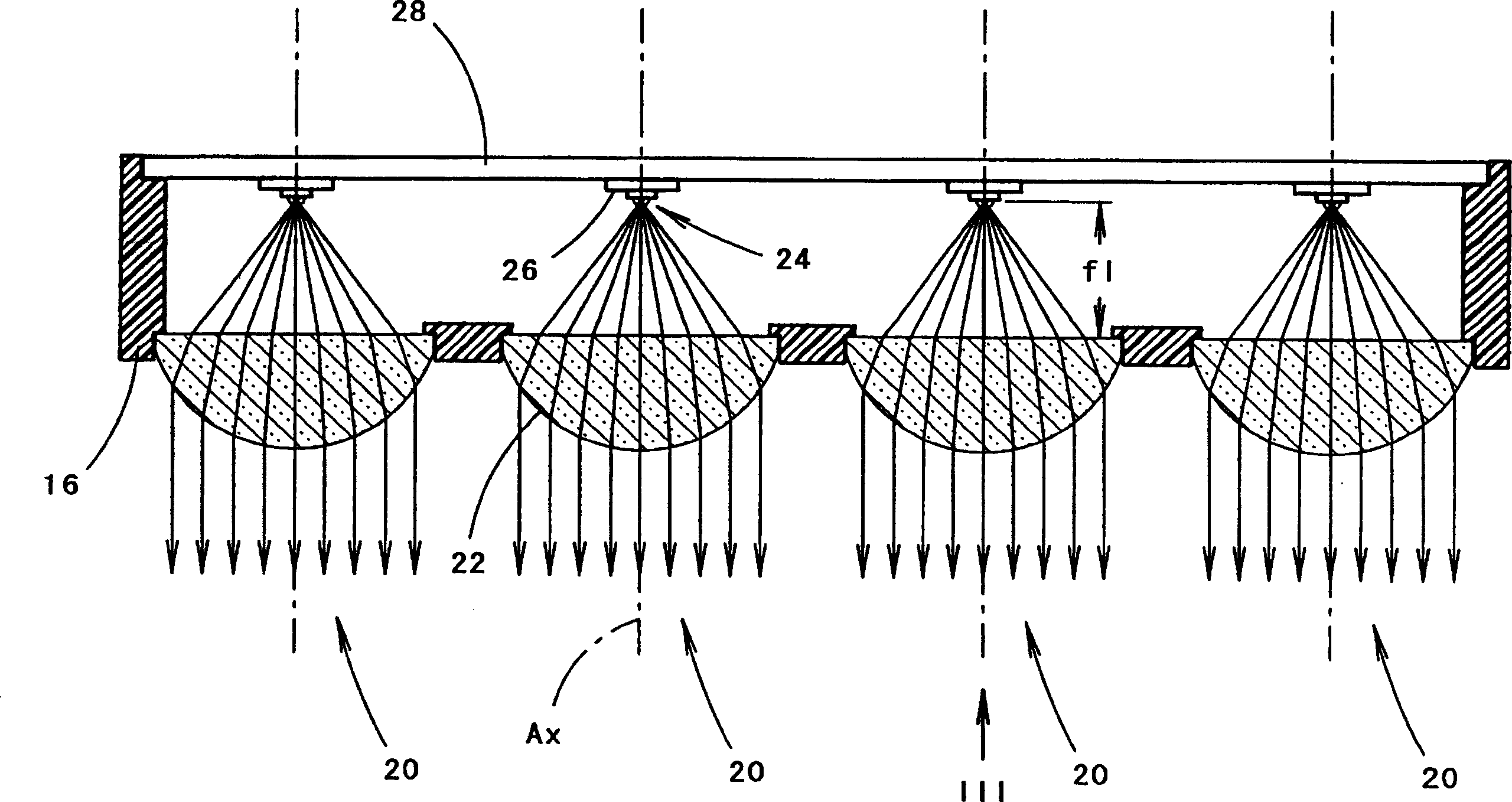
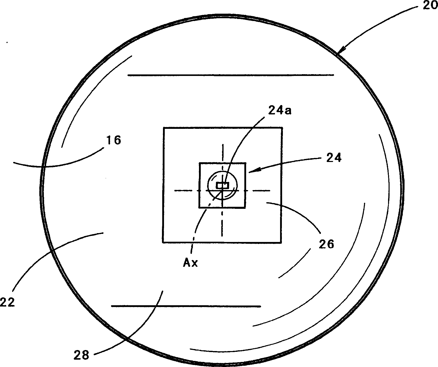
[0046]As shown in the figure, the vehicle headlamp 10 of this embodiment is housed in a lamp chamber formed by a lamp body 12 and a translucent cover 14 mounted on the front end opening, and 12 lamp units are accommodated in three layers up and down. structure. That is, four lamp units 20 are arranged on the lower stage, four lamp units 30 are arranged on the middle stage, and four lamp units 40 are arranged on the upper stage.

[0047] The translucent cover 14 forms a transparent strip-shaped area located in the center of the vertical direction, and in its lower area, a plurality of diffusion lens elements 14s for diffusing the illumination light from the four lamp units 20 located on the lower floor to the horizontal direction are formed. Vertical st...


PUM


Abstract

The headlight has lighting device units (20,30,40) forming a projection that overlaps at a height. Each of the lighting device units includes a light source having a photo emissive semiconductor device e.g. LED, with photo-emissive chips disposed horizontally along a row and turned towards front. A projection lens placed in front of the light source projects an inversed image of the light source towards front of the headlight. An Independent claim is also included for a lamp forming a light distribution pattern having a horizontal component and an oblique component overlapping at a height.

Description

technical field [0001] The present invention relates to a vehicle headlamp having a light distribution pattern having a horizontal cut-off line at an upper end and an upper protrusion protruding upward from the horizontal cut-off line. Background technique [0002] Generally speaking, as described in "Patent Document 1", for example, a vehicle headlamp has a light distribution pattern having a horizontal cut-off line and an upper protrusion protruding upward from the horizontal cut-off line at the upper end, In this way, the glare will not be given to the driver of the oncoming vehicle and the distant visibility of the driver of the vehicle can be ensured. [0003] The structure of the vehicle headlamp disclosed in this "Patent Document 1" is that the second reflector for forming an upper protrusion for light irradiation is supported on the lamp unit body so that it can rotate in the horizontal direction. By rotating, the position of the upper protrusion can be moved in the...

Claims


Application Information

Patent Timeline
Patent Type & Authority Applications(China)
IPC IPC(8): B60Q1/04B60Q1/12B60Q1/18F21S8/10F21S8/12F21V5/00F21V13/00F21V14/02F21W101/10F21Y101/02H01L25/075
CPCB60Q1/18H01L33/54F21S48/1233H01L25/0753B60Q1/12F21S48/1154F21S48/1163H01L33/20B60Q2300/122F21S48/1747F21Y2101/02F21Y2113/00F21Y2115/10F21S41/143F21S41/153F21S41/155F21S41/28F21S41/663H01L2924/0002H01L2924/00F21S41/20F21S41/32F21W2102/00
Inventor 石田裕之
Owner KOITO MFG CO LTD
Why Eureka
Try Eureka