A method and device for demodulating three-dimensional blade tip clearance

A three-dimensional blade tip and blade tip clearance technology, which is applied in the field of devices for demodulating three-dimensional blade tip clearance and demodulating three-dimensional blade tip clearance, can solve the problems of poor calculation accuracy, high result error, huge calculation amount, etc., and achieve demodulation. Efficiency improvement, excellent anti-interference effect

Active Publication Date: 2019-11-08
XI AN JIAOTONG UNIV
View PDF6 Cites 2 Cited by
  • Summary
  • Abstract
  • Description
  • Claims
  • Application Information

AI Technical Summary

Problems solved by technology

[0006] In the previous work, the double-circle coaxial fiber optic bundle sensor was only used to detect one-dimensional radial displacement, and there was only a one-dimensional spatial output characteristic model for simplified processing, while the received light intensity of the fiber bundle when observing the displacement changes of the reflecting surface in three-dimensional space When changing the law, it is not difficult to find that the light intensity changes caused by radial clearance, axial inclination and circumferential inclination are coupled together. Therefore, the output characteristic function form of the optical fiber bundle under the influence of three-dimensional blade tip clearance is extremely complicated. From the positive direction The calculation amount of the function to solve the three-dimensional tip clearance is very large, and the calculation accuracy is very poor; in addition, because the nonlinear relationship between the output light intensity and the three-dimensional tip clearance is very high, the calibration data using the neural network method is cumbersome and complicated, and the demodulation The result error is high

Method used


Image

  • A method and device for demodulating three-dimensional blade tip clearance
  • A method and device for demodulating three-dimensional blade tip clearance
  • A method and device for demodulating three-dimensional blade tip clearance

Examples


Embodiment Construction

[0028] The technical solution of the present invention will be further described below in conjunction with the accompanying drawings and specific embodiments.

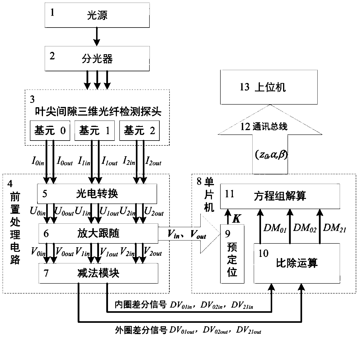
[0029] The present invention provides a device for demodulating the three-dimensional tip clearance, such as figure 1 As shown, it includes the tip clearance three-dimensional optical fiber detection probe 3 for obtaining optical signals, and the tip clearance three-dimensional optical fiber detection probe 3 includes three independent primitives, namely the origin primitive, the axial auxiliary primitive and the circumferential auxiliary primitive ; The optical signal is provided through the light source and the optical splitter, and the specific optical signal emitted by the light source is divided into three optical signals provided to the three primitives through the optical splitter.

[0030] Wherein the three primitives output the obtained optical signal as three outer ring light intensity signals and three inner...


PUM


Abstract

The invention discloses a method and device for demodulating three-dimensional tip clearance. The device includes a tip clearance three-dimensional fiber detection probe having three independent elements, wherein the three independent elements acquire optical signals, outer ring optical signals and inner ring optical signals are further outputted, the three sets of outer ring optical signals and inner ring optical signals from the three independent elements are acquired by a pre-processing circuit, the pre-processing circuit includes a photoelectric conversion module, an amplification followermodule and a subtraction module, the three sets of outer ring optical signals and inner ring optical signals are converted by the photoelectric conversion module into six paths of corresponding photoelectric signals, and the six paths of corresponding photoelectric signals are amplified by the amplification follower module and outputted to the subtraction module and a single-chip microcomputer module. The device is advantaged in that the inner and outer ring light intensity signals of the three elements of the three-dimensional tip clearance fiber sensing probe are taken as input, the three sets of differential ratio signals are obtained through pairwise difference and ratio division, and the three-dimensional tip clearance information is demodulated through the three sets of differentialratio signals.

Description

technical field [0001] The invention belongs to the technical field of three-dimensional blade tip demodulation of a three-dimensional output characteristic function of a double-circle coaxial optical fiber bundle sensing unit, relates to a method for demodulating a three-dimensional blade tip gap, and also relates to a device for demodulating a three-dimensional blade tip gap. Background technique [0002] Double-circle coaxial optical fiber bundle is a displacement sensor with simple structure, small size and strong anti-interference ability. The ratio signal is output after the received light intensity signal is compared and divided, so as to eliminate the influence of nonlinear interference factors such as optical power fluctuation interference and uneven reflection surface encountered by the optical fiber bundle in the optical transmission process, and has high engineering application value . [0003] In practical engineering applications, especially when non-contact m...

Claims


Application Information

Patent Timeline
Patent Type & Authority Patents(China)
IPC IPC(8): G01B11/14
CPCG01B11/14
Inventor 张小栋谢思莹熊逸伟牛杭刘洪成邸发贵
Owner XI AN JIAOTONG UNIV
Why Eureka
Try Eureka