Reaction cup motion path control method and device

A technology of motion path and control method, which is applied in the direction of analyzing materials and instruments, can solve problems such as tube jamming and falling into through holes, and achieve the effects of reducing volume, preventing tube jamming, and simplifying the control process

Active Publication Date: 2022-03-15
MACCURA MEDICAL INSTR CO LTD
View PDF8 Cites 0 Cited by
  • Summary
  • Abstract
  • Description
  • Claims
  • Application Information

AI Technical Summary

Problems solved by technology

In the cuvette loading device with this structure, in the process of loading cuvettes, it is easy for the cuvette behind the first cuvette to fall into the through hole before the switch assembly is closed, so that multiple reactions The cups are piled up between the next station under the through hole and the position of the through hole, which prevents the switch assembly from closing, resulting in tube jamming

Method used


Image

  • Reaction cup motion path control method and device
  • Reaction cup motion path control method and device
  • Reaction cup motion path control method and device

Examples


Embodiment Construction

[0048] In order to better understand the present invention, the reaction cup motion path control method and apparatus of the embodiment of the present invention will be described in detail below with reference to the accompanying drawings.

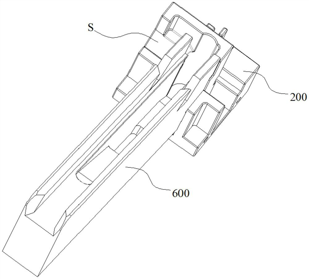
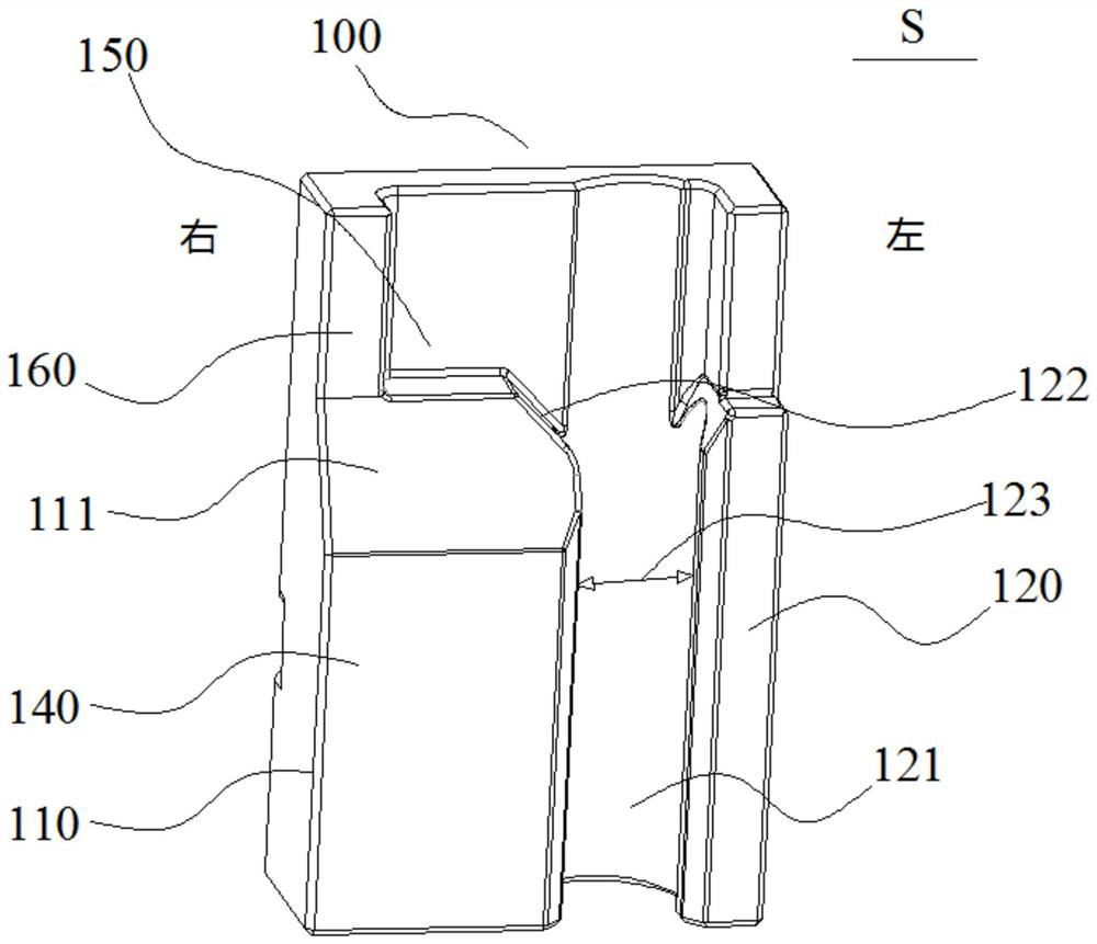
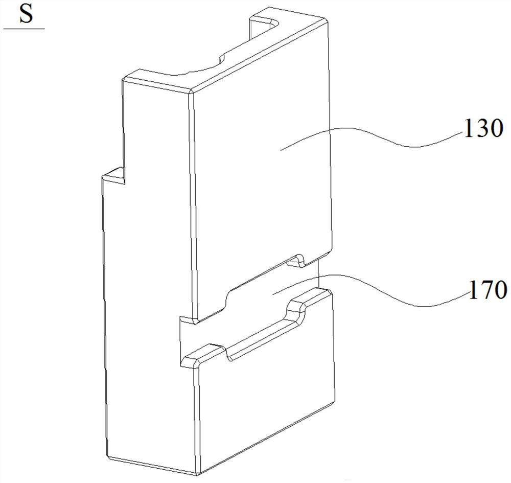
[0049] Such as Figures 1 to 12 As shown, the reaction cup push block S, including pushing the block body 100, and the push block body 100 is provided with a cup barrier portion 110 and the cup guiding portion 120, and the cup barrier portion 110 is used to block the waiting station. The reaction cup N, and the cup guiding portion 120 is used to guide the single reaction cup N of the waiting station W to the next station.

[0050] The push block body 100 can move in the push block moving passage 201 on the base 200, by moving the push block body 100, the cup barrier portion 110 or cup guiding portion 120 on the push block body 100 can be made to the waiting station W Docking, the reaction cup located at the waiting station W can be blocked by t...


PUM


Abstract

The present invention provides a method and device for controlling the movement path of cuvettes. The method includes the steps: in response to the demand for adding cuvettes, the controller controls the movement of the cuvette pushing block to the second limit state, thereby releasing the cuvette pushing block. The body blocking part blocks the first reaction cup located at the waiting station, so that the first reaction cup located at the waiting station enters the cup guide channel of the reaction cup push block, and the controller controls the reaction cup push block to move to the first cuvette. In a limit state, the cup guide channel is connected to the next station, so that the first cuvette entering the cup guide channel is transported to the next station, so that the reaction cups arranged in the cuvette transport groove next to the first cuvette The cuvettes of the cuvettes enter the waiting station, and the cuvettes entering the waiting station are blocked at the waiting station by the cup blocking part. In this method, only one cuvette can be transported from the waiting station to the next station at a time, which can simplify the control process of the components in the next station.

Description

Technical field [0001] The present invention relates to the field of in vitro, especially a reaction cup motion path control method and apparatus. Background technique [0002] In an in vitro diagnostic analyzer, the reaction cup is delivered from the reaction cup silo to the load channel to the load channel, queued in the loading passage and sequentially entered the next designated position, such as a reagent disk. A through hole corresponding to the loading channel outlet is provided on the through hole, and the switch assembly that functions on the open and closing hole is provided on the through hole. When the reaction cup is required, the open and closing holes are opened by the switch assembly, so that the loading channel is outlet. The first reaction cup at the point is dropped into the through hole. In the process of loading the reaction cup, the reaction cup loading device is prone to the switching assembly, and the reaction cup located behind the first reaction cup has ...

Claims


Application Information

Patent Timeline
Patent Type & Authority Patents(China)
IPC IPC(8): G01N35/04
CPCG01N35/04G01N2035/0489G01N2035/0462
Inventor 陈建波张业祥李浩
Owner MACCURA MEDICAL INSTR CO LTD
Why Eureka
Try Eureka