
Shielding device

A technology of shielding device and connection hole, which is applied in the field of testing equipment, can solve problems such as inability to achieve complete shielding and affect test accuracy, and achieve the effect of improving test efficiency and accuracy

Active Publication Date: 2019-01-04
COMBA TELECOM TECH (GUANGZHOU) CO LTD
View PDF8 Cites 1 Cited by
  • Summary
  • Abstract
  • Description
  • Claims
  • Application Information

AI Technical Summary

Problems solved by technology

The traditional shielding device cover cannot achieve a close fit with the box, and cannot achieve complete shielding, which affects the accuracy of the test

Method used


Image

  • Shielding device
  • Shielding device
  • Shielding device

Examples


Embodiment Construction

[0030] In order to make the object, technical solution and advantages of the present invention clearer, the present invention will be further described in detail below in conjunction with the accompanying drawings and specific implementation methods. It should be understood that the specific embodiments described here are only used to explain the present invention, and do not limit the protection scope of the present invention.

[0031] It should be noted that when an element is referred to as being “disposed on” or “fixed on” another element, it may be directly on another element or there may be an intervening element. When an element is referred to as being "fixed on" another element, or "fixedly connected" to another element, it may be detachably fixed or non-detachably fixed therebetween. When an element is referred to as being "connected" or "rotatably connected" to another element, it can be directly connected to the other element or intervening elements may also be pres...


PUM


Abstract

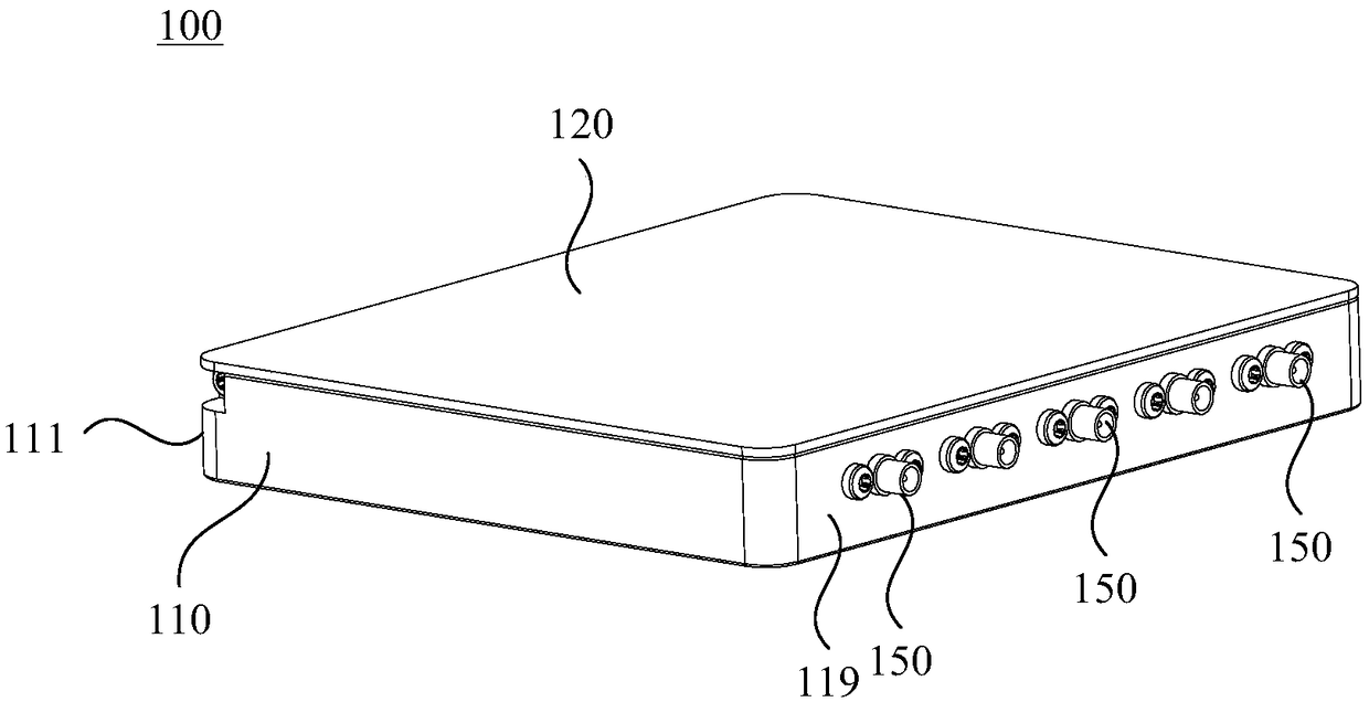
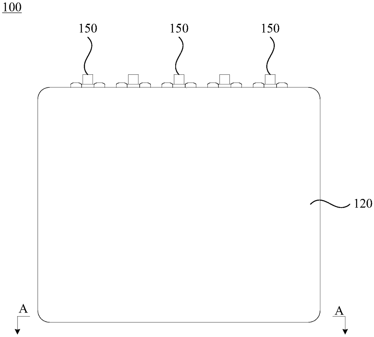
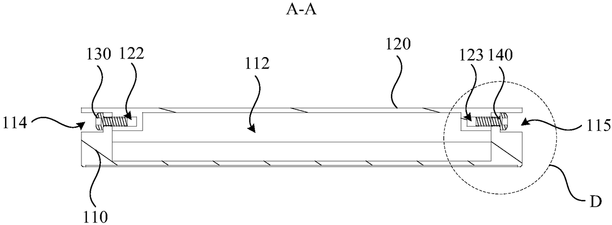
The invention discloses a shielding device comprising a box which is provided with a test chamber with an opening, wherein the first side wall of the test chamber is provided with a first sealing part; and a cover which comprises a first end and a second end which are opposite, wherein the first end is rotatably connected with the first side wall, and the first end is provided with a second sealing part capable of being cooperated with the first sealing part in a sealing way. When the cover is in the first state, the second end is separated from the box so that the opening is communicated withthe outside. When the cover is in the second state, the second sealing part is cooperated with the first sealing part in a sealing way and the cover seals the test chamber. According to the shieldingdevice, close cooperation between the cover and the box can be realized so as to realize complete shielding and enhance the test accuracy.

Description

technical field [0001] The invention relates to the technical field of testing equipment, in particular to a shielding device. Background technique [0002] PCB (Printed Circuit Board, printed circuit board) or related electronic devices are susceptible to external electromagnetic interference during the relevant testing process. Therefore, shielding devices are usually used to shield or offset external electromagnetic interference to improve the accuracy of the test. sex. [0003] The traditional shielding device includes a box with a test chamber and a cover that can match the box. During use, after placing the test element in the test chamber on the box, the cover is placed on the test chamber. The opening of the box and the use of fasteners such as screws to achieve the cooperation of the cover and the box. The traditional shielding device cover cannot achieve a close fit with the box, and cannot achieve complete shielding, which affects the accuracy of the test. Con...

Claims


Application Information

Patent Timeline
Patent Type & Authority Applications(China)
IPC IPC(8): G01R1/18
CPCG01R1/18
Inventor 丘培卜力
Owner COMBA TELECOM TECH (GUANGZHOU) CO LTD
Learn More