Display device and image transmission method used by it

A technology of display device and transmission method, which is applied to static indicators, cathode ray tube indicators, instruments, etc., and can solve problems such as data loss

Inactive Publication Date: 2006-11-29
MITAC COMP (SHUN DE) LTD +1
View PDF0 Cites 0 Cited by
  • Summary
  • Abstract
  • Description
  • Claims
  • Application Information

AI Technical Summary

Problems solved by technology

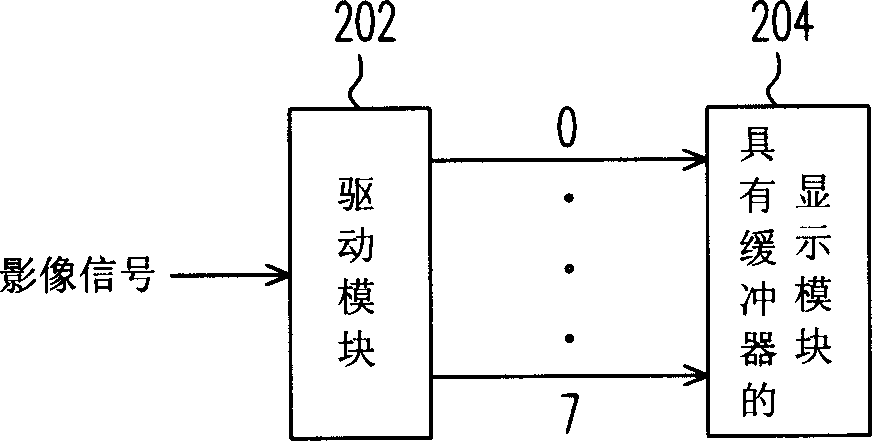
[0006] And if the display panel used has a buffer (buffer), such as figure 2 As shown, an image signal is input into the drive module 202, and the image signal obtained after signal processing by the drive module 202 is output in units of 8 bits, in the form of a red (R) signal, a green (G) signal and a blue (B) signal. ) signals are separated and sent to the display module 204 with a buffer. Usually, the central processing unit supports this method, but many general-purpose input and output (GPIO) pins are still used.
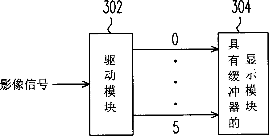
[0007] In addition, there is another transmission method, such as image 3 As shown, the display panel in the figure also has a buffer. When an image signal is input to the driver module 302, the image signal obtained after the signal processing by the driver module 302 is output in units of 6 bits, and the red (R) signal , the green (G) signal and the blue (B) signal are separated and transmitted to the display module 302 with a buffer. Although this transmission method has improved the above-mentioned shortcomings, another problem has arisen because the previous 8 bits are 256 color output, but after changing to 6-bit, only 64-color output, so if there is no color you want, you can only choose a color with a similar color at most, so there may be a problem of data loss.

Method used


Image

  • Display device and image transmission method used by it
  • Display device and image transmission method used by it
  • Display device and image transmission method used by it

Examples


Embodiment Construction

[0021] Please refer to Figure 4 , Figure 4 It is a diagram of a display device according to a preferred embodiment of the present invention. The display device includes a driving module 402 and a display module 404 .

[0022] In this embodiment, the driving module 402 may be a central processing unit, but not limited thereto, which is used to receive image signals, and use the internal color mixing module 402a to perform color mixing processing on the received image signals.

[0023] After the above-mentioned processing, an image signal is generated, and the image signal is output in units of 6 bits, among which the red (R) signal, green (G) signal and blue (B) signal are separately transmitted to the buffer with a buffer The display module 404, wherein the display module can be a liquid crystal display panel, and its internal buffer temporarily stores the received signal, and sends it out again after the required signal is available.

[0024] In this way, not only can a ...


PUM


Abstract

A display device consists of driving module with color mixing module and display module. it is featured as using said driving module to receive image signal, outputting an image signal by driving module after received image signal is processed with color mixing module and using display module to receive image signal outputted by driving module.

Description

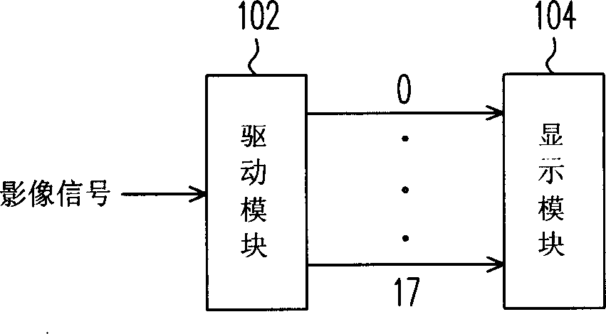
technical field [0001] The present invention relates to a device and a signal transmission method, and in particular to a display device and an image transmission method. Background technique [0002] At present, the transmission of general images is first passed through a driver module, and then processed in the driver module and then output to the display module. [0003] The drive module includes a central processing unit, and when an image signal is input, the received image signal is processed by the central processing unit and then an image signal is output. [0004] When the driving module outputs the image signal to the display module, it can use many ways. [0005] Among them such as figure 1 As shown, an image signal is input into the drive module 102, and the image signal obtained after signal processing by the drive module 102 is output to the display module 104 in units of 18 bits. Although this will speed up the transmission speed, it is relatively Many Gene...

Claims


Application Information

Patent Timeline
Patent Type & Authority Applications(China)
IPC IPC(8): G09G5/00G09G3/20
Inventor 吴佳泽
Owner MITAC COMP (SHUN DE) LTD
Why Eureka
Try Eureka