A New Type of Ring USB Disk
A ring, a new type of technology, applied in the direction of record carriers used in machines, instruments, computer parts, etc., can solve the problems of U disk loss, U disk damage and other problems, and achieve the goal of not easy to lose, prolong the service life, and easy to find Effect
- Summary
- Abstract
- Description
- Claims
- Application Information
AI Technical Summary
Problems solved by technology
Method used
Image
Examples
Embodiment 1
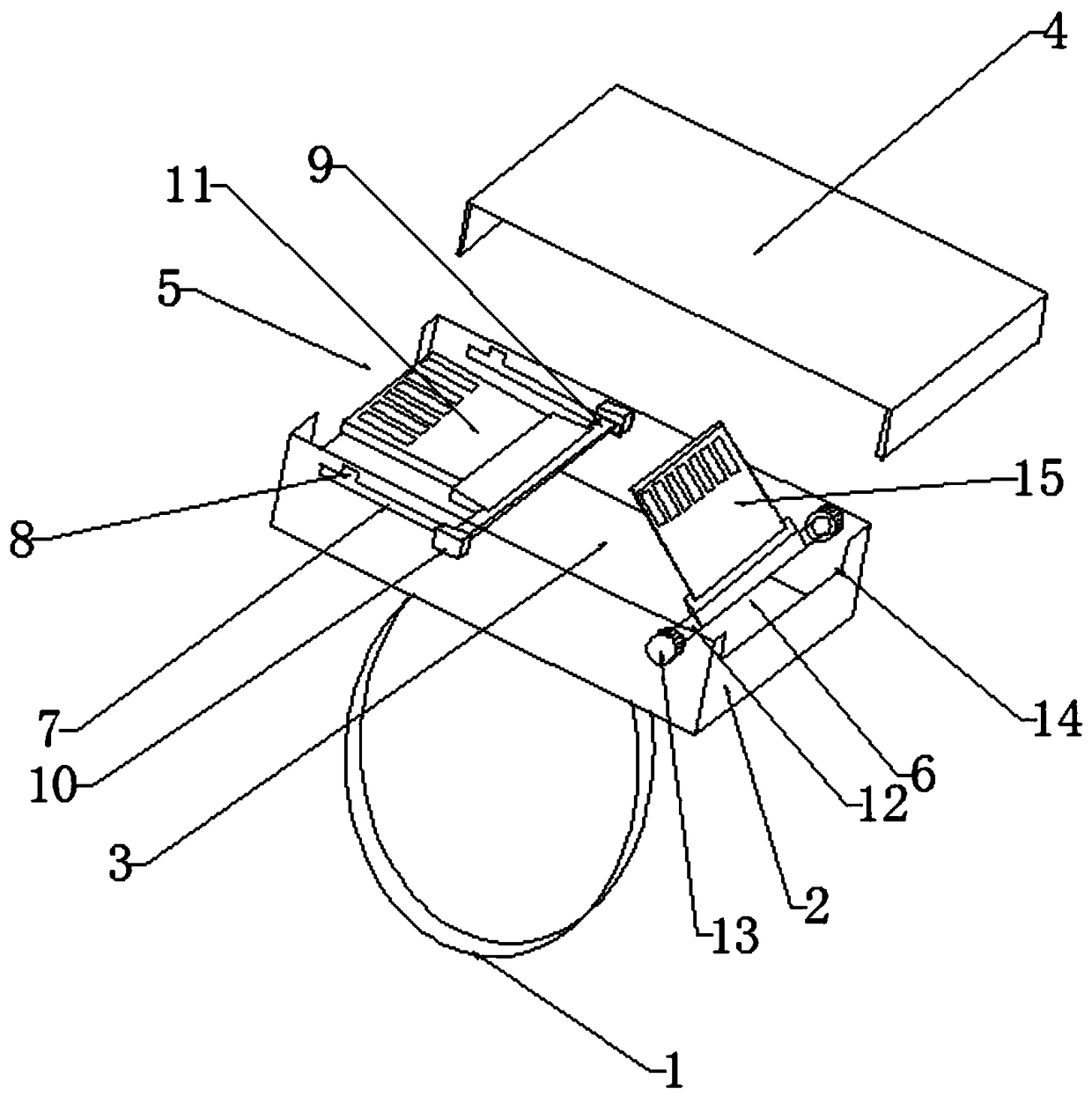
[0027] A new type of ring U disk, comprising a ring ring 1, and a U disk body magnetically connected to the ring ring 1, characterized in that: the U disk body includes a bottom box 2, and the top of the bottom box 2 is provided with an opening 3, The opening 3 is provided with a cover plate 4 magnetically connected to the bottom box 2; the bottom box 2 is provided with a sliding U disk assembly 5 and an overturning U disk assembly 6 which are movably connected with the bottom box 2. The first way of use is to manually move and slide the U disk assembly 5 directly to move the U disk out of the bottom box 2. The second way of use is to open the cover plate 4 and flip the U disk assembly 6 out of the bottom box 2. Turn over 180°, so that the flipped U disk assembly 6 is placed outside the bottom box 2, and is normally connected to other device ports for normal use. The main body of the U-disk is magnetically fixedly connected to the ring 1 to prevent the U-disk assembly from bei...
Embodiment 2
[0029] Based on Embodiment 1, the opposite sides of the bottom box 2 are provided with a through groove 7 to facilitate the movement of the sliding U disk assembly 5, and the through groove 7 is provided near the end surface of the bottom box 2 for fixing the sliding Groove 8 of U disk assembly 5. The through groove 7 is convenient for the sliding U disk assembly 5 to move back and forth at the through groove 7. When the sliding U disk slides to a suitable position, it is fixed at the groove 8, and then the entire sliding U disk assembly 5 is fixed in position. , the sliding U disk assembly 5 can be used normally to prevent the sliding U disk assembly 5 from moving backward when it is connected to the device port.
Embodiment 3
[0031] Based on Embodiment 2, the sliding U disk assembly 5 includes a slide bar 9 slidably connected to the through groove 7, a moving block 10 fixedly connected to both ends of the slide bar 9, a U disk slot on the outer wall of the slide bar 9, and a The first U disk 11 in the U disk groove; the sliding rod 9 is interference fit with the groove 8 . The U disk groove and part of the slide bar 9 are placed inside the bottom box 2, the first U disk 11 is placed in the U disk groove, the moving block 10 is fixedly connected with the slide bar 9, and then the moving block 10 is manually controlled to move in the through groove 7, Slide to the groove 8, fix the slide bar 9 in the groove 8, the first U disk 11 protrudes out of the bottom box 2, and it can be used. The groove 8 fixes the slide bar 9 to prevent the first U disk 11 from When the device port is connected, slide the U disk assembly 5 back.
PUM
 Abstract
Description
Claims
Application Information
 - R&D
- Intellectual Property
- Life Sciences
- Materials
- Tech Scout
- Unparalleled Data Quality
- Higher Quality Content
- 60% Fewer Hallucinations
Browse by: Latest US Patents, China's latest patents, Technical Efficacy Thesaurus, Application Domain, Technology Topic, Popular Technical Reports.
© 2025 PatSnap. All rights reserved.Legal|Privacy policy|Modern Slavery Act Transparency Statement|Sitemap|About US| Contact US: help@patsnap.com

