
Multi-channel flow tube

A multi-channel, flow tube technology, applied in the field of multi-channel flow tubes, can solve problems such as impact, reduced sensitivity of Coriolis flowmeters, and unfavorable meters

Inactive Publication Date: 2019-01-04
MICRO MOTION INC
View PDF8 Cites 0 Cited by
  • Summary
  • Abstract
  • Description
  • Claims
  • Application Information

AI Technical Summary

Problems solved by technology

When the Reynolds number is low (usually due to high viscosity), there are flow profile related effects which lead to a decrease in the sensitivity of the Coriolis flow meter
Larger gauges (which have smaller tube length to tube diameter ratios) are more adversely affected
Larger gauges also require thicker tube walls to accommodate high pressure fluid

Method used


Image

  • Multi-channel flow tube
  • Multi-channel flow tube
  • Multi-channel flow tube

Examples


Embodiment Construction

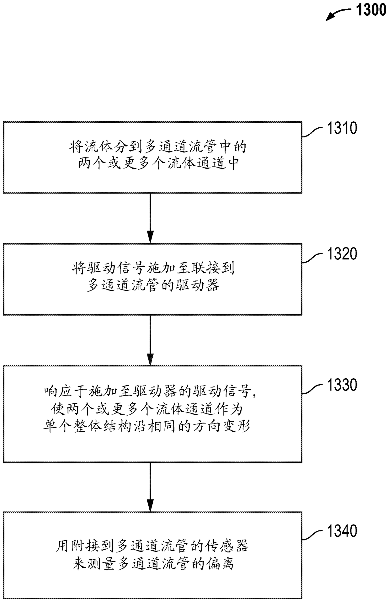
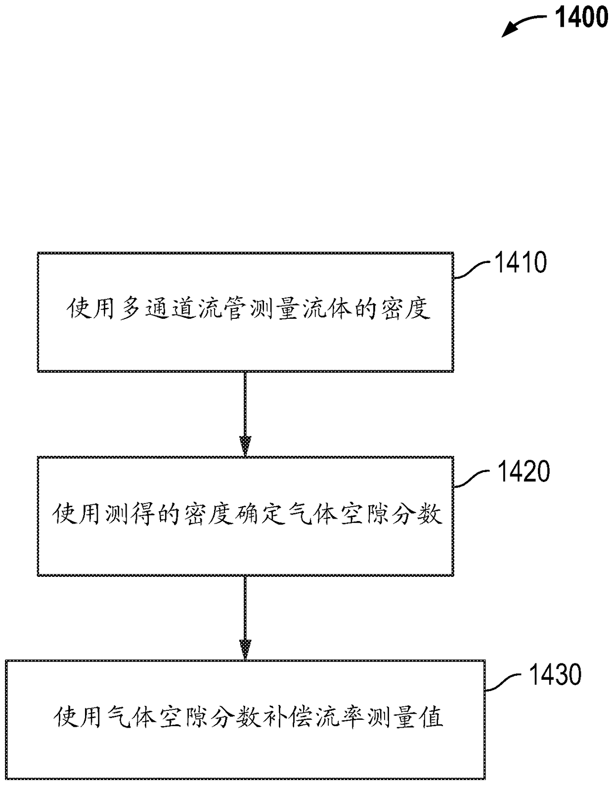
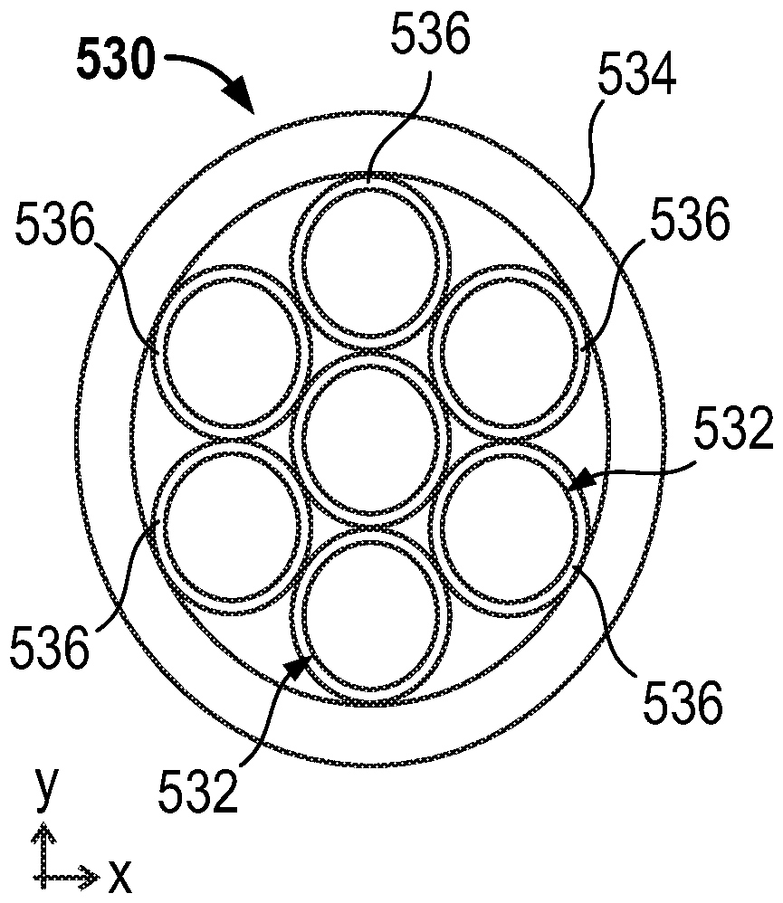
[0042] Figure 1 to Figure 14 The and following descriptions depict specific examples to teach those skilled in the art how to make and use the best mode of embodiments of multi-channel flowtubes. For the purpose of teaching inventive principles, some conventional aspects have been simplified or omitted. Those skilled in the art will appreciate variations from these examples that fall within the scope of the present description. Those skilled in the art will appreciate that the features described below can be combined in various ways to form multiple variations of multi-channel flow tubes. As a result, the embodiments described below are not limited to the specific examples described below, but only by the claims and their equivalents.

[0043] The vibrating meter includes meter electronics communicatively coupled to the meter assembly. The multi-channel flow tube is part of the metering assembly. A multi-channel flow tube includes two or more fluid channels. A driver is ...


PUM


Abstract

A vibratory meter (5) including a multi-channel flow tube (130) is provided. The vibratory meter (5) includes a meter electronics (20) and a meter assembly (10) communicatively coupled to the meter electronics (20). The meter assembly (10) includes the multi-channel flow tube (130, 330, 430, 530) comprising two or more fluid channels (132, 332, 432, 532) surrounded by a tube wall (134, 334, 434, 534). The two or more fluid channels (132, 332, 432, 532) and the tube wall (134, 334, 434, 534) comprise a single integral structure. A driver (180) is coupled to the multi-channel flow tube (130, 330, 430, 530). The driver (180) is configured to vibrate the multi-channel flow tube (130, 330, 430, 530). The two or more fluid channels (132, 332, 432, 532) and the tube wall (134, 334, 434, 534) areconfigured to deform in the same direction as the single integral structure in response to a drive signal applied to the driver (180).

Description

technical field [0001] Embodiments described below relate to vibration sensors, and more particularly to multi-channel flow tubes. Background technique [0002] Vibrating meters, such as, for example, vibrating density meters and Coriolis flow meters, are commonly known and are used to measure mass flow and other information about material flowing through a pipe in a vibrating meter. Exemplary Coriolis flow meters are disclosed in US Patent 4,109,524, US Patent 4,491,025 and Re. 31,450. These vibrating meters have a metering assembly with one or more tubes in a straight or curved configuration. Each piping configuration in a Coriolis mass flow meter, for example, has a set of natural modes of vibration, which may be of the simple bending type, torsional type, or coupled type. Each tube can be driven to oscillate in a preferred mode. When no flow is passing through the flowmeter, the driving force applied to the pipe(s) causes all locations along the pipe(s) to oscillate w...

Claims


Application Information

Patent Timeline
Patent Type & Authority Applications(China)
IPC IPC(8): G01F1/76G01F1/84G01N9/00G01F15/08
CPCG01F1/76G01F1/8486G01F1/8495G01F15/08G01N2009/006G01F1/8477G01F15/02
Inventor M.J.贝尔J.温斯坦M.A.施洛瑟F.S.肖伦伯格
Owner MICRO MOTION INC
Learn More