
Shaver and blade structure thereof

A shaver and blade technology, applied in the field of shavers, can solve problems such as easy sticking, and achieve the effect of avoiding sticking

Pending Publication Date: 2019-01-08
浙江海顺电工有限公司
View PDF0 Cites 0 Cited by
  • Summary
  • Abstract
  • Description
  • Claims
  • Application Information

AI Technical Summary

Problems solved by technology

[0005] The purpose of the present invention is to provide a shaver and its blade structure to solve the problem that the rear end of the moving knife of the shaver and the rear end of the fixed knife are easily stuck to death

Method used


Image

  • Shaver and blade structure thereof
  • Shaver and blade structure thereof
  • Shaver and blade structure thereof

Examples


Embodiment Construction

[0025] The core of the present invention is to provide a shaver and its blade structure to solve the problem that the rear end of the moving knife and the rear end of the fixed knife of the shaver are easily stuck to death.

[0026] In order to enable those skilled in the art to better understand the technical solutions provided by the present invention, the present invention will be further described in detail below in conjunction with the accompanying drawings and specific embodiments.

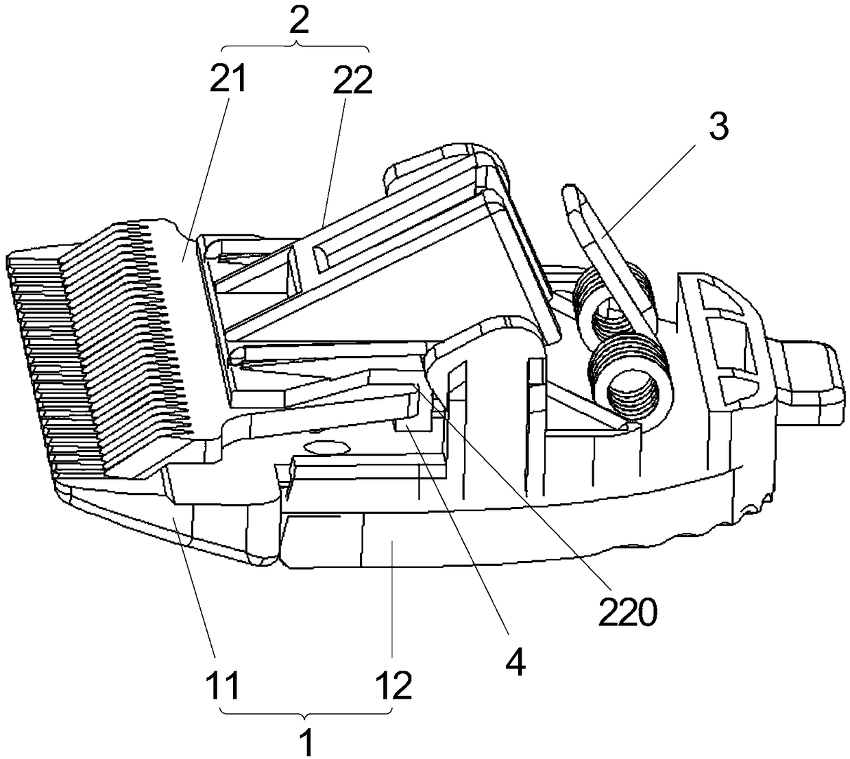
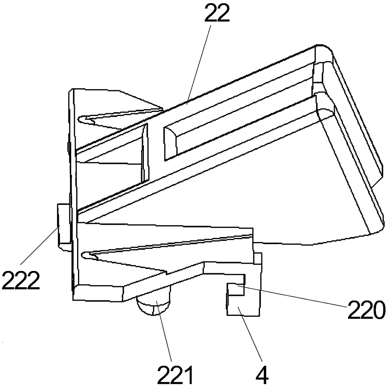
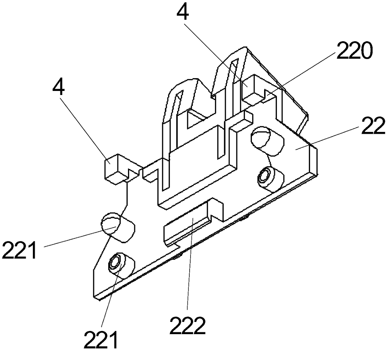
[0027] Such as Figure 1-Figure 6 As shown, the blade structure of a shaver provided by the embodiment of the present invention includes a fixed knife assembly 1 and a movable knife assembly 2 that slides horizontally and laterally with the fixed knife assembly 1 , and the movable knife assembly 2 is pressed together by a pressure elastic element 3 On the fixed knife assembly 1, the fixed knife assembly 1 includes a fixed knife 11 and a fixed knife fixing frame 12 fixedly connected with the ...


PUM


Abstract

The invention discloses a shaver and a blade structure thereof. The blade structure comprises a fixed cutter assembly and a movable cutter assembly in sliding fit with the fixed cutter assembly horizontally in the transverse direction. The movable cutter assembly is pressed on the fixed cutter assembly through a pressure elastic element. The fixed cutter assembly comprises a fixed cutter and a fixed cutter fixing frame fixedly connected with the fixed cutter. The movable cutter assembly comprises a movable cutter and a movable cutter fixing frame, and the movable cutter fixing frame and the movable cutter move synchronously. An abrasion resistant separation piece is arranged between the rear end of the movable cutter and the rear end of the fixed cutter. According to the blade structure, when the shaver works, a motor drives the movable cutter fixing frame to move, then the movable cutter fixing frame drives the movable cutter to do horizontal and transverse cutting motion relative tothe fixed cutter, the abrasion resistant separation piece is arranged between the rear end of the movable cutter and the rear end of the fixed cutter, thus the rear end of the movable cutter and the rear end of the fixed cutter are isolated from each other, mutual direction friction is avoided, a friction effect is generated by the rear end of the movable cutter or the rear end of the fixed cutterand the abrasion resistant separation piece, and in this way, the complete sticking phenomenon of the rear end of the movable cutter and the rear end of the fixed cutter can be avoided.

Description

technical field [0001] The invention relates to the technical field of shaver, in particular to a shaver and its blade structure. Background technique [0002] The shaver is a tool for shaving hair, which includes a fixed knife assembly and a moving knife assembly. The fixed knife assembly includes a fixed knife fixing frame and a fixed knife. The moving knife assembly includes a moving knife fixing frame and a moving knife. Both the front ends of the knife and the fixed knife are provided with toothed cutting edges. When the shaver is working, the moving knife moves horizontally and laterally relative to the fixed knife, so that the toothed cutting edge of the moving knife produces a relatively horizontal transverse shearing relative to the toothed cutting edge of the fixed knife. The effect, so as to realize the shaving of hair. [0003] In order to ensure the parallel cutting movement of the moving knife head relative to the fixed knife head, it is necessary to restrict ...

Claims


Application Information

Patent Timeline
IPC IPC(8): B26B19/06B26B19/38
CPCB26B19/06B26B19/3813B26B19/384
Inventor 钟海勇
Owner 浙江海顺电工有限公司
Learn More