Chain board turning machine

A technology of turning machine and chain plate, applied in the direction of conveyor, transportation and packaging, can solve the problems of breakage, continuous force of conveyor chain plate 13, increase the cost of chain plate replacement, etc. Easy to break effect

Active Publication Date: 2019-01-08
YANGZHOU WELDON TRANSMISSION EQUIP CO LTD
View PDF8 Cites 4 Cited by
  • Summary
  • Abstract
  • Description
  • Claims
  • Application Information

AI Technical Summary

Problems solved by technology

[0004] In order to ensure the strength of the inner plate 11 in the existing chain plate turning machine, the bearings 14 are installed at intervals on the inner plate 11, so that the bearings 14 on the inner plate 11 cannot allow the conveyor chain plate 13 to be continuously stressed, and it is easy to make the end of the conveyor chain plate 13 The head is broken due to uneven force, which reduces the service life of the conveyor chain plate 13 and increases the replacement cost of the chain plate

Method used


Image

  • Chain board turning machine
  • Chain board turning machine
  • Chain board turning machine

Examples


Embodiment Construction

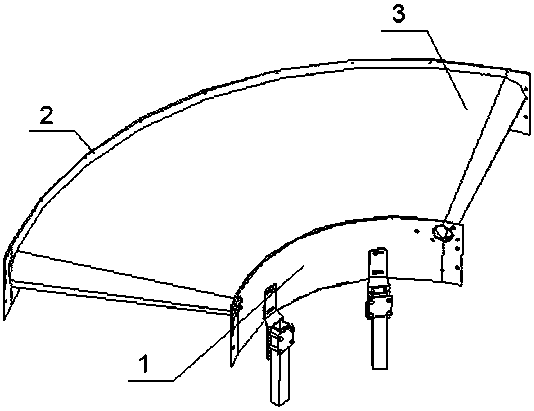
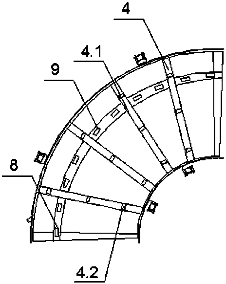
[0017] like Figure 1-5 As shown, the present invention includes an arc-shaped inner plate 1 and an outer plate 2, an annular conveyor chain plate 3 is arranged between the inner plate 1 and the outer plate 2, and a plurality of intervals are arranged below the conveyor chain plate 3 along the conveying direction. The idler device 4 includes a connecting pipe 4.1 connected between the inner plate 1 and the outer plate 2, and a plurality of first support bearings 4.2 arranged at intervals are installed on the connecting pipe 4.1.

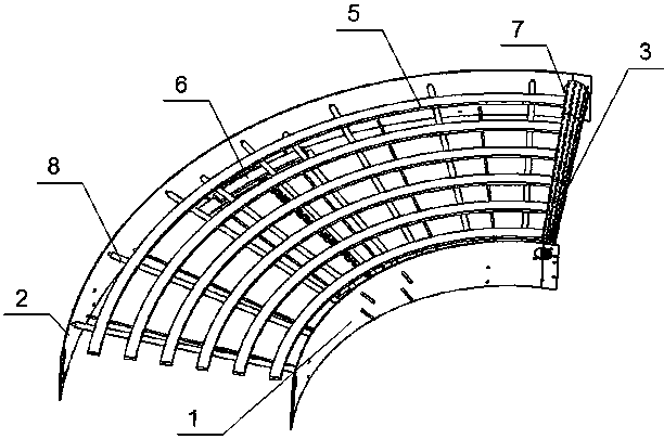
[0018] The conveyor chain plate 3 is provided with a plurality of upper guide rails 5 for the support and guidance of the upper conveyor chain plate 3, and a plurality of lower guide rails 6 for the support and guidance of the lower conveyor chain plate 3. The upper guide rails 5 and the lower guide rails 6 are supported by intervals. The rod 8 is installed between the inner plate 1 and the outer plate 2, and the back of the conveying chain plate 3 i...


PUM


Abstract

The invention discloses a chain board turning machine and relates to the field of conveying equipment. The chain board turning machine comprises an arc-shaped inner side board and an outer side board;an annular conveying chain board is arranged between the inner side board and the outer side board; a plurality of carrier roller devices arranged at intervals are arranged below the conveying chainboard in the conveying direction; and the conveying chain board is internally provided with a plurality of upper guide rails used for supporting and guiding of the upper layer of the conveying chain board and a plurality of lower guide rails used for supporting and guiding of the lower layer of the conveying chain board. The chain board turning machine is characterized in that the back face of theconveying chain board is provided with a plurality of limiting bearings in the conveying direction, and the limiting bearings are attached to the outer side walls of the upper guide rail on the outermost side and the lower guide rail on the outermost side. The limiting bearings are arranged on the back face of the conveying chain board and attached to the outer side walls of the upper guide railon the outermost side and the lower guide rail on the outermost side, so that the stress point of the conveying chain board moves to the outer side from the inner side, continuous stress is achieved,it is ensured that the conveying chain board can be smoothly and stably conveyed, the problem that the inner side end face of the conveying chain board is stressed unevenly and is broken is eliminated, and the service life of the chain board is prolonged.

Description

technical field [0001] The invention relates to the field of conveying equipment, in particular to a chain plate turning machine. Background technique [0002] When the chain plate transmission needs a certain turning angle, it can be realized by using the chain plate turning machine. like Figure 5 As shown, the existing chain plate turning machine includes an inner plate 11 and an outer plate 12, a conveying chain plate 13 is arranged between the inner plate 11 and the outer plate 12, and the inside of the conveying chain plate 13 is provided with multiple A bearing assembly 14, the bearing assembly 14 includes the upper bearing 15 that cooperates with the upper conveying chain plate 13 and the lower bearing 16 that cooperates with the lower conveying chain plate 13, when turning, the conveying chain plate 13 is subjected to the effect of centripetal force to the inner plate continuously 11 fits and contacts with the bearing assembly 14, and the bearing assembly 14 acts a...

Claims


Application Information

Patent Timeline
Patent Type & Authority Applications(China)
IPC IPC(8): B65G21/22
CPCB65G21/22
Inventor 吴宝东
Owner YANGZHOU WELDON TRANSMISSION EQUIP CO LTD
Why Eureka
Try Eureka