Electric wheel stopping device and three-dimensional garage carrying hanging bracket using the same
A backstop device and three-dimensional garage technology, applied in the direction of buildings, building types, buildings, etc. where cars are parked, can solve the problems of vehicle movement, failure to prevent car movement, accidents, etc., and achieve convenient vehicle entry and exit, convenient equipment maintenance, The effect of preventing vehicle movement
- Summary
- Abstract
- Description
- Claims
- Application Information
AI Technical Summary
Problems solved by technology
Method used
Image
Examples
Embodiment 1
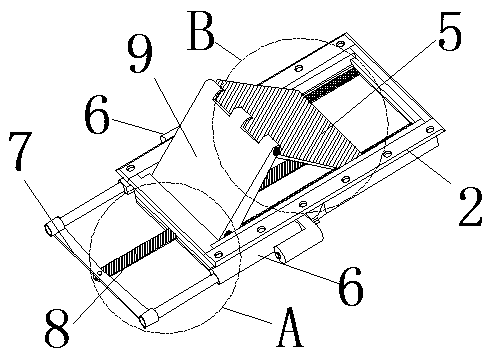
[0071] Example 1. Such as Figure 1-7 As shown, an electric wheel backstop device is characterized in that: the wheel backstop device includes a frame body 2 with a rectangular cross section; Inside the upward square hole 3;
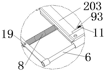
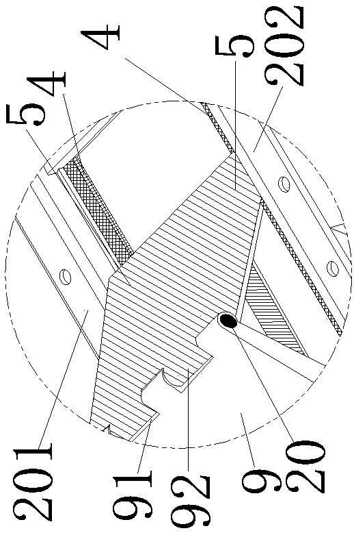
[0072] The right side of the left side 201 of the frame body 2 and the bottom end of the left side of the right side 202 are respectively provided with longitudinal rails 4, and the rear side of the front side 203 of the frame body 2 is hinged with a first square panel 9;
[0073] The rear end of the first square panel 9 is hinged with a second square panel 5; the left and right sides of the rear end of the second square panel 5 can slide on the longitudinal rail 4 respectively; 6. The front ends of the telescopic shafts of the two electric telescopic devices 6 are connected to a horizontal plate 7, and the middle part of the horizontal plate 7 is connected to a longitudinal tie rod 8, and the rear end of the longitudinal tie rod 8 is hinged to the re...
Embodiment 2
[0081] Example 2. Such as Figure 8-10 As shown, the difference between the present embodiment and the embodiment is that there are two wheel backstop devices 37, which are located at the left front and right rear ends of the vehicle-loading plate respectively. An anti-shake bar 39 is provided on the vehicle hanger.
Embodiment 3
[0082] Example 3. Such as Figure 8 , Figure 9 As shown, the difference between the present embodiment and the first embodiment is that the front end of the first square panel 9 is hinged to the rear side of the front side 203 of the frame body 2 through a front transverse connecting hinge 10 provided transversely with several hinge axes.
[0083] Example 3. Such as Figure 11-Figure 12As shown, the difference between this embodiment and the embodiment is that: the left and right sides of the bottom surface of the rear end of the second square panel 5 are respectively provided with side bearings 14, and a horizontal rotation shaft 15 is connected between the bearings 14 on both sides, and the rear of the longitudinal tie rod 8 The end is connected with the transverse rotation shaft 15.
PUM
 Abstract
Description
Claims
Application Information
 - R&D
- Intellectual Property
- Life Sciences
- Materials
- Tech Scout
- Unparalleled Data Quality
- Higher Quality Content
- 60% Fewer Hallucinations
Browse by: Latest US Patents, China's latest patents, Technical Efficacy Thesaurus, Application Domain, Technology Topic, Popular Technical Reports.
© 2025 PatSnap. All rights reserved.Legal|Privacy policy|Modern Slavery Act Transparency Statement|Sitemap|About US| Contact US: help@patsnap.com


