Hydraulic ejecting type mounting in-place method for generator of large gas turbine

A technology of generators and hydraulic jacks, applied in the direction of supporting machines, mechanical equipment, engine bases, etc., to achieve the effect of simple mechanical equipment, simple operation methods, and short construction period

Inactive Publication Date: 2019-01-08
POWERCHINA SEPCO1 ELECTRIC POWER CONSTR CO LTD
View PDF5 Cites 2 Cited by
  • Summary
  • Abstract
  • Description
  • Claims
  • Application Information

AI Technical Summary

Problems solved by technology

[0005] The purpose of the present invention is to provide a hydraulic pushing installation method for a large gas turbine generator, which is used to solve the technical problem of installing a large gas turbine generator in a narrow space

Method used


Image

  • Hydraulic ejecting type mounting in-place method for generator of large gas turbine
  • Hydraulic ejecting type mounting in-place method for generator of large gas turbine
  • Hydraulic ejecting type mounting in-place method for generator of large gas turbine

Examples


Embodiment Construction

[0024] In order to clearly illustrate the technical features of the present solution, the present invention will be described in detail below through specific implementation methods and in conjunction with the accompanying drawings. It should be noted that components illustrated in the figures are not necessarily drawn to scale. Descriptions of well-known components and techniques are omitted herein to avoid unnecessarily limiting the present invention.

[0025] A method for hydraulic push-type installation and placement of a large gas turbine generator includes the following steps.

[0026] 1. Generator foundation backfill

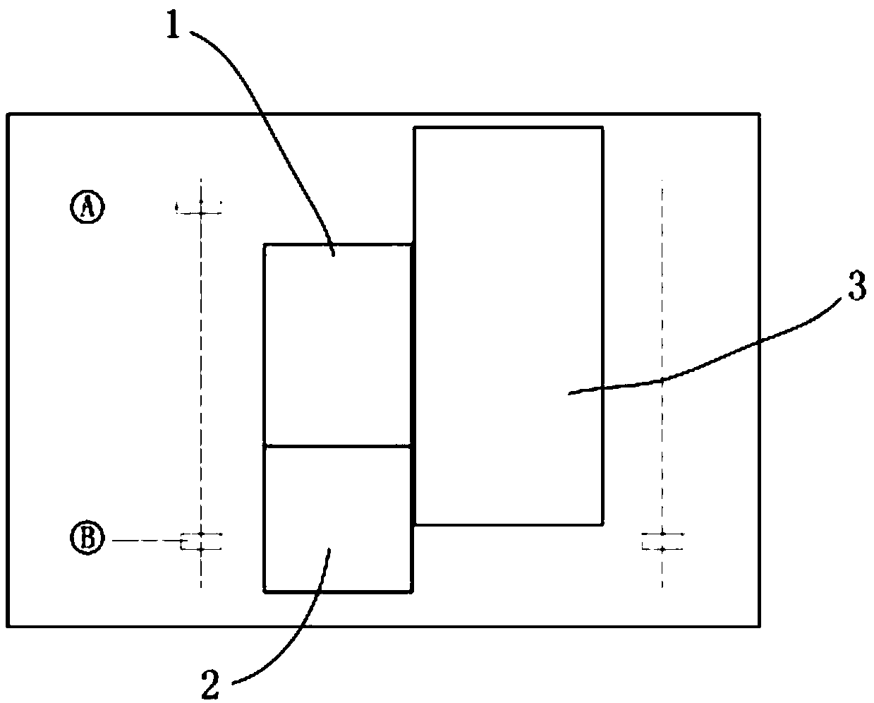
[0027] Such as figure 1 As shown, the base area 1 of the generator is located beside the base area 2 of the gas turbine. Backfill the longitudinal side of the generator foundation area 1 to the specified height and compact it, so as to ensure that the bottom elevation of the generator 7 reaches the required elevation after the arrival of the generator ...


PUM


Abstract

The invention aims to provide a hydraulic ejecting type mounting in-place method for a generator of a large gas turbine for solving the technical problem that the generator of the large gas turbine ismounted in place in a narrow space. The hydraulic ejecting type mounting in-place method for the generator of the large gas turbine comprises the following steps: I, backfilling a generator base; II,arranging a sleeper platform; and III, transferring the generator.

Description

technical field [0001] The invention relates to the technical field of installation and placement of large gas turbine generators, in particular to a hydraulic push-type installation method for large gas turbine generators. Background technique [0002] Gas-fired generator sets, gas turbines and their supporting generators are mostly arranged on the zero-meter floor of the factory building. At the same time, in order to ensure that the shaft centers of the gas turbines and generators are at the same height, the foundation of the generator is generally 2 to 3 meters higher than the foundation of the gas turbine. At present, in the design of the gas-fired unit plant, the design of the corresponding lifting facilities (such as the driving of the turbine room) above the generator is not considered. Therefore, gas turbine generators cannot use the generator hoisting method of conventional thermal power units, and can only rely on external large-scale lifting facilities, such as l...

Claims


Application Information

Patent Timeline
Patent Type & Authority Applications(China)
IPC IPC(8): F16M5/00
CPCF16M5/00
Inventor 缑海琛杜传国曹启强杨德丰
Owner POWERCHINA SEPCO1 ELECTRIC POWER CONSTR CO LTD
Why Eureka
Try Eureka