
Methods of oxy-combustion power generation using low heating value fuel

a technology of oxy-combustion and low heating value, which is applied in the direction of liquefaction, machines/engines, lighting and heating apparatus, etc., can solve the problems of low heating value gas readily being utilized in gas turbines, low efficiency of such rankine cycle power plants, and general lower efficiency associated with use of such low heating value fuel

Inactive Publication Date: 2010-12-30
CLEAN ENERGY SYST
View PDF31 Cites 180 Cited by
  • Summary
  • Abstract
  • Description
  • Claims
  • Application Information

AI Technical Summary

Benefits of technology

[0017]Accordingly, a primary object of the present invention is to provide a system that uses existing conventional gas turbines which minimize development, capital and operation and maintenance costs.
[0025]Another object of the present invention is to provide a method for beneficial use of a waste gas discharged from an industrial process while keeping the waste gas from contaminating the environment.

Problems solved by technology

A primary limiting factor on efficiency for such Rankine cycle power plants is the turbine inlet temperature for such steam turbines and the ability of boilers to heat the steam to higher temperatures for efficiency improvement.
Issues not yet satisfactorily solved with prior art gas turbine and combined cycle power plants include avoidance of emissions of greenhouse gases, especially CO2, and other pollutants, as well as the flexibility to employ hydrocarbon fuels that are readily available and yet not suitable for combustion within gas turbine power plants.
Such low heating value gases cannot readily be utilized in gas turbines because gas turbines have been optimized for combustion with natural gas or other fuels with a heating value similar to or higher than that of natural gas.
However, such steam power plants require a customized boiler, and suffer from the generally lower efficiencies associated with use of such a low heating value fuel.
Also, the pollutants from the exhaust stack of such plants are combined with excess air and are difficult to separate.
Furthermore, the carbon dioxide generated by combustion of such low heating value gases ends up being exhausted from the boiler after having been mixed with the oxygen depleted air used for combustion, so that the carbon dioxide generated by combustion of the low heating value fuel is not readily kept away from the atmosphere.

Method used


Image

  • Methods of oxy-combustion power generation using low heating value fuel
  • Methods of oxy-combustion power generation using low heating value fuel
  • Methods of oxy-combustion power generation using low heating value fuel

Examples


Embodiment Construction

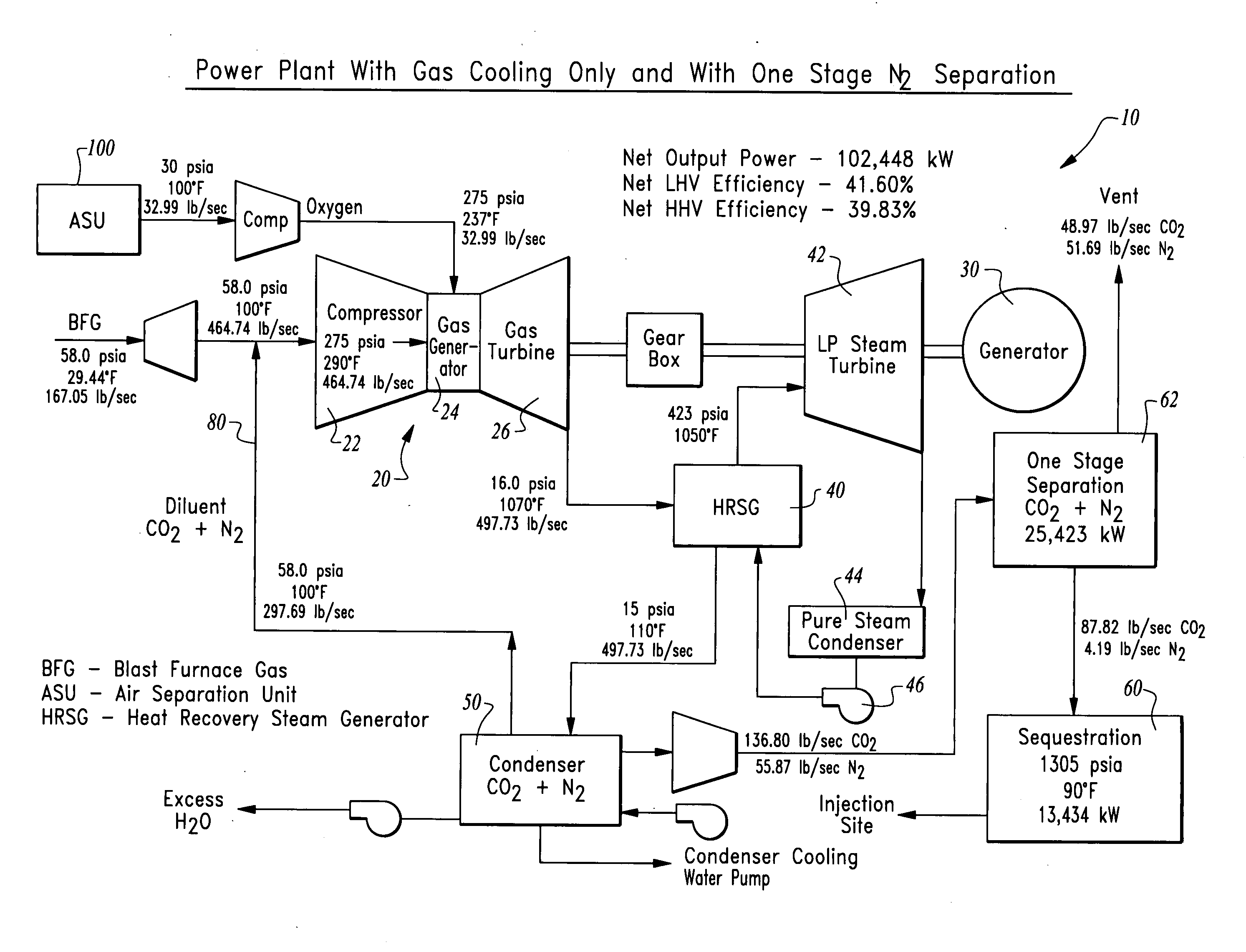
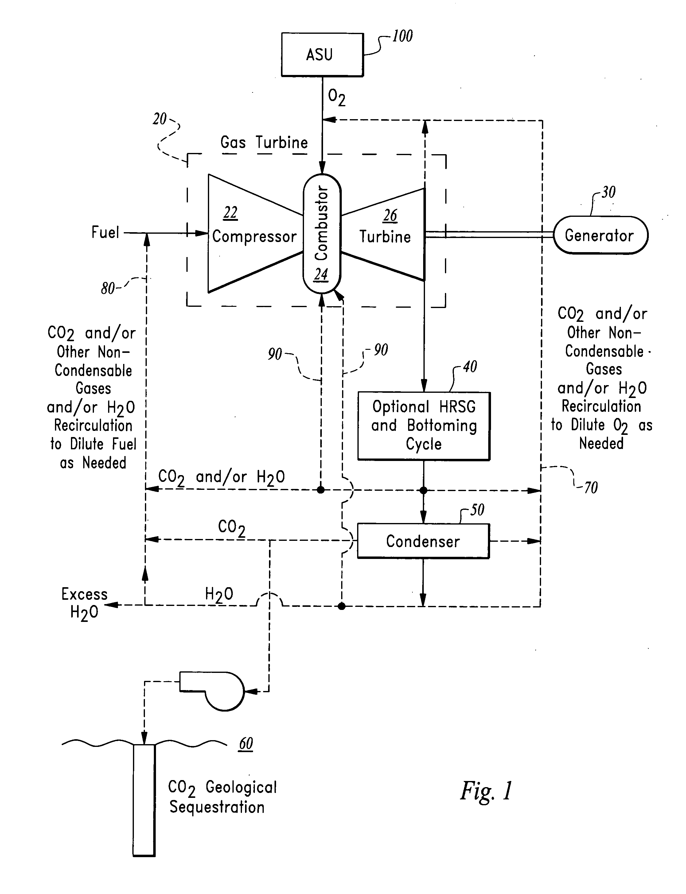
[0031]Referring to the drawings, wherein like reference numerals represent like parts throughout the various drawing figures, reference numeral 10 is directed to a power generation system with a reverse circuit gas turbine 20 (FIGS. 1 and 2) centrally featured therein. In this example system a standard gas turbine 20 can be utilized to combust a low heating value fuel, such as blast furnace gas (BFG). The fuel and air circuits of the gas turbine 20 are reversed so that the low heating value fuel is introduced into a compressor 22 of the gas turbine 20 while the oxygen is directed into a combustor 24 of the gas turbine 20 through the “fuel inlet.” In a second embodiment, the low heating value fuel is combusted within an oxy-combustion gas generator 120 power generation system 110 featuring recirculation of non-condensable gases such as those which are often produced by combustion of a low heating value fuel that includes non-condensable gas producing constituents therein, such as nit...


PUM


Abstract

An oxy-combustor is provided to combust oxygen with gaseous low heating value fuel. A compressor upstream of the combustor compresses the fuel. The combustor produces a drive gas including steam and carbon dioxide as well as other non-condensable gases in many cases, which pass through a turbine to output power. The drive gas can be recirculated to the combustor, either through the compressor, the oxygen inlet or directly to the combustor. Recirculation can occur before or after a condenser for separation of a portion of the water from the carbon dioxide. Excess carbon dioxide and steam is collected from the system. The turbine, combustor and compressor can be derived from an existing gas turbine with fuel and air / oxidizer lines swapped.

Description

CROSS-REFERENCE TO RELATED APPLICATIONS[0001]This application claims benefit under Title 35, United States Code §119(e) of U.S. Provisional Application No. 61 / 209,324 filed on Mar. 4, 2009.FIELD OF THE INVENTION[0002]The following invention relates to fuel combustion power generation systems, and especially oxy-combustion power generation systems which minimize atmospheric pollutant generation and release by combustion with oxygen, rather than air. More particularly, this invention relates to power generation systems which are configured to combust fuels having a low heating value than natural gas and which potentially contain a large proportion of pollutants therein, in low or non-polluting ways and to generate power.BACKGROUND OF THE INVENTION[0003]For over a century baseline electric power has been largely supplied through power plants combusting a hydrocarbon fuel to energize a working fluid that has been passed through a turbine where the working fluid is expanded and the turbi...

Claims


Application Information

Patent Timeline
IPC IPC(8): F01K23/10F02C3/04F02C6/00F02C3/30
CPCF01K23/10F01K23/16Y02E20/16F02C6/18Y02E20/14F02C3/34Y02E20/32Y02E20/34F25J3/04533F25J3/04563F25J3/04581F25J2260/80
Inventor ANDERSON, ROGER E.VITERI, FERMINHOFFMAN, LAWRENCE C.HOFFMAN, CHERYL LYNNPRONSKE, KEITH L.
Owner CLEAN ENERGY SYST
Learn More