Turbine blades made from multiple single crystal cast superalloy segments

Inactive Publication Date: 2001-12-18
SIEMENS ENERGY INC
View PDF43 Cites 180 Cited by
  • Summary
  • Abstract
  • Description
  • Claims
  • Application Information

AI Technical Summary

Problems solved by technology

Although components with such features have been developed for aircraft engines, the larger size of power generation turbine components provides a crucial challenge.
To date, casting trials have been unable to produce defect-free large components in any significant yields.
Currently, however, the required bonding technology for advanced superalloys, including single crystal materials such as CMSX-4 that are targeted for use in ATS-class engines, is not available.
The 
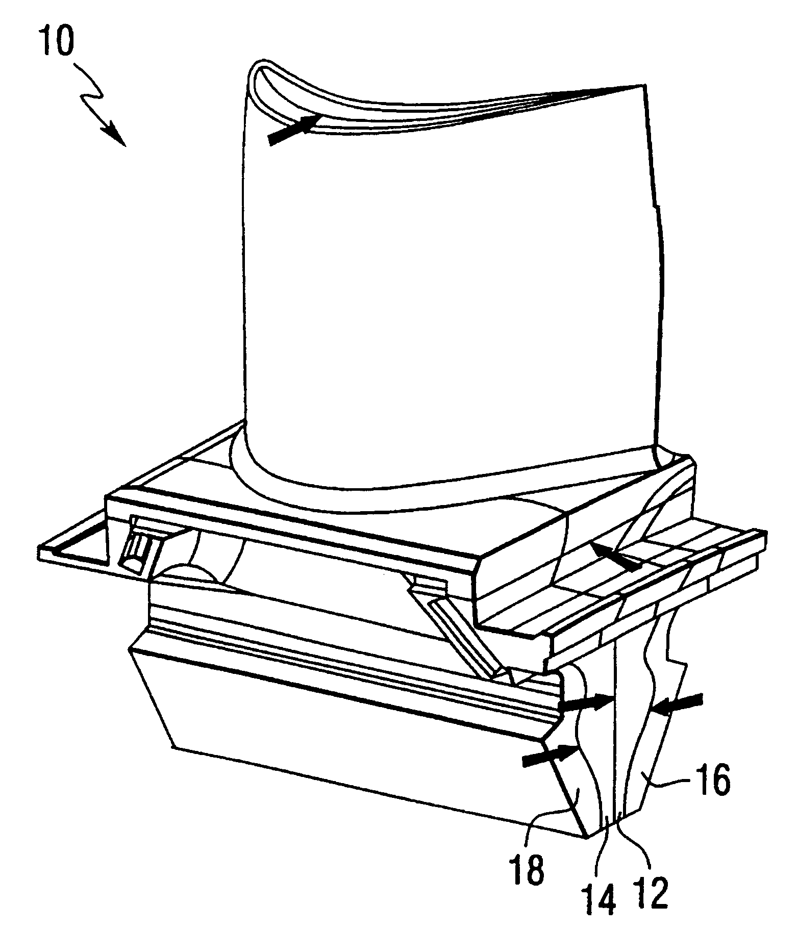
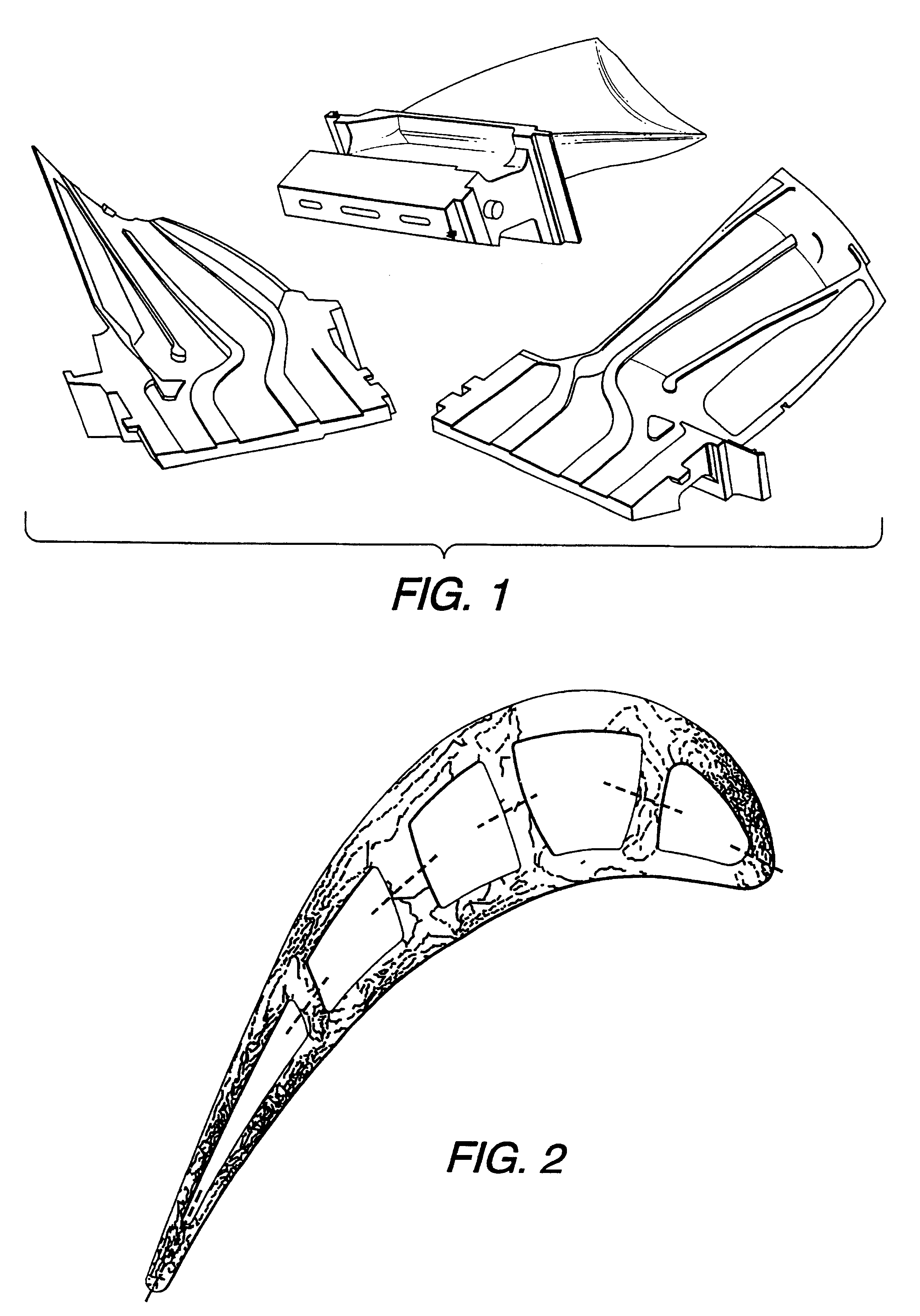
present method allows the production of large, high quality turbine blades by joining small, high quality sections, in comparison with prior attempts to cast turbine blades as single pieces which have produced very low yields with concomitant high individual component costs.
Currently less than 20 percent yield of blades as single castings is forecast for large, land based turbine blades, with the primary difficulty being the thickness of the casting.
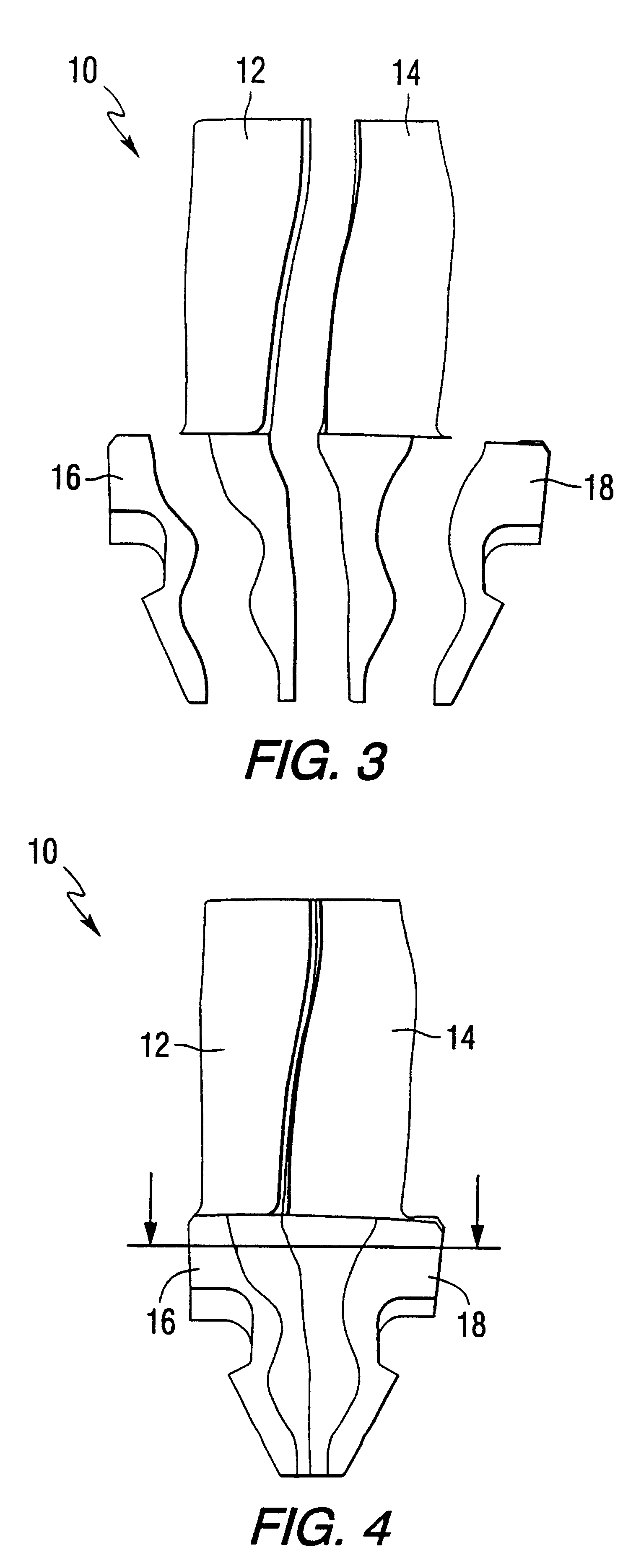
Since polycrystalline and single crystal alloys have different chemical compositions (see Table 1) identical matching of the bond foil composition to each side of a single crystal-to-polycrystal bond joint may not be possible.
In particular, it is generally not be possible for the conventionally cast polycrystalline material to withstand the high solution heat treat temperatures employed for the single crystal material.
Furthermore, some expensive elements such as rhenium may not be desired in the foil in order to reduce costs.
Furthermore, the stresses created by these profiling techniques must be sufficiently low such that they do not induce recrystallization from the deformed layer of cold work during s

Method used


Image

  • Turbine blades made from multiple single crystal cast superalloy segments
  • Turbine blades made from multiple single crystal cast superalloy segments
  • Turbine blades made from multiple single crystal cast superalloy segments

Examples


Embodiment Construction

The effect of bonding foil chemistry and thermal treatments on the microstructure and mechanical properties were assessed experimentally. Initially, several bonding foil chemistries and thermal processes were employed to generate samples for metallographic assessment. The processes that produced the most homogeneous chemistry and microstructure across the bond line and throughout the base metal were selected for further assessment by testing the tensile and creep properties.

A CMSX-4 base material was supplied in the as-cast conditions as single crystal slabs approximately 9.5.times.76.2.times.152.4 mm (0.375.times.3.times.6 inches). The bonding media were obtained as 50 .mu.m (0.002 inch) thick commercial bonding foils.

The boron levels of the bonding foils are actually B ranges since two of the foils were supplied in several forms with slightly different boron levels: Ni-Flex 110 was supplied with 1.3%, 1.7% and 2.5% B levels and Ni-Flex 120 was supplied with 1.5%, 1.7% and 1.9% B l...


PUM

PropertyMeasurementUnit
Fractionaaaaaaaaaa
Fractionaaaaaaaaaa
Percent by massaaaaaaaaaa

Abstract

Large gas turbine blades made from separate cast segments of superalloys are disclosed. The turbine blade is designed such that bond lines between adjacent segments are placed in low stress regions of the blade. The cast superalloy segments of the blades are aligned and fitted together with specified tolerances. The turbine blade segments are then joined by transient liquid phase bonding, followed by a controlled heat treatment which produces the desired microstructure in the bond region. The method allows for the production of large, high quality turbine blades by joining small, high quality cast superalloy sections, in comparison with prior attempts to cast large turbine blades as single pieces which have produced very low yields and high individual component costs.

Description

The present invention relates to power generation combustion gas turbines, and more particularly relates to blades for such turbines made from multiple segments of cast superalloys.BACKGROUND INFORMATIONState-of-the-art blades and vanes that are employed in modern, high efficiency power generation combustion turbine engines rely on high quality materials such as single crystal alloys and precise control of the part's internal and external dimensions. Because of the large size of these parts, cost-effective manufacturing is being pursued by several routes.Land-based gas turbines, such as the advanced turbine system (ATS) which is under development, require cost-effective high performance components fabricated from advanced materials. First and second row turbine blades and vanes include complex internal and external geometries, and should be fabricated from defect-free materials. Although components with such features have been developed for aircraft engines, the larger size of power...

Claims


Application Information

Patent Timeline
IPC IPC(8): B23K20/02B23K35/30B23P15/04C22C19/05C22F1/10C30B11/00F01D5/28F01D5/14F01D5/18B23K20/16B23P15/02C22C19/03C22F1/00C30B29/52
CPCB23H9/10B23K20/16B23K35/3033B23P15/04C22C19/057C22F1/10C30B11/00F01D5/147F01D5/18F01D5/184F01D5/28B23K20/023C30B29/52Y10T428/12431B23K35/304B23K2201/001Y02T50/67Y02T50/671Y02T50/673Y02T50/676Y10T428/12271F05D2230/23F05D2230/40F05D2300/607Y10T428/12944Y10T428/12347B23K2101/001Y02T50/60
Inventor BURKE, MICHAEL A.FREYER, PAULA D.HEBBAR, MOHAN A.SETH, BRIJ B.SWARTZBECK, GARY W.ZAGAR, THOMAS WALTER
Owner SIEMENS ENERGY INC
Why Eureka
Try Eureka