Power supplying and taking system of rail vehicle

A rail vehicle and electric system technology, applied in the field of power supply and power supply system, can solve the problems of vehicle power outage, negative impact on vehicle safety operation, power supply network load stability, continuous and stable power supply, etc., to achieve stable power supply Effect

Pending Publication Date: 2019-01-11
贾兴鲁
View PDF0 Cites 4 Cited by
  • Summary
  • Abstract
  • Description
  • Claims
  • Application Information

AI Technical Summary

Problems solved by technology

[0003] At present, the common way of power supply and power supply is suitable for solving the problem of vehicle power supply in rail transit with switch mechanism, but it cannot solve the problem of continuous and stable power supply for vehicles in monorail traffic without switch mechanism when passing the switch.
Because this kind of guide rail will have a vacancy at the turnout, the traditional power supply design will cause the vehicle to have a power outage problem at the turnout for a period of time
The current technology can only be powered by batteries in the vacant local section, and needs to enter and exit the trolley line frequently, which will have a negative impact on the safe operation of the vehicle and the load stability of the power supply network

Method used


Image

  • Power supplying and taking system of rail vehicle
  • Power supplying and taking system of rail vehicle
  • Power supplying and taking system of rail vehicle

Examples


Embodiment 1

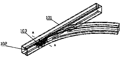
[0074] Embodiment 1, the guide rail 101 has a switch section and a non-switch section; the first power supply device 11 is continuously provided on the switch section and the non-switch section of the guide plate 102 . The first power supply device 11 is arranged along with the guide rail 101 along the entire running direction of the rail car 103 as the only power supply line. The first power supply device 11 is continuously arranged at the turnout and the non-turnout of the guide plate 102 . So that no matter where the rail car 103 is on the guide rail 101, the first power supply device 11 is in contact with the first power taking device 12, and the rail car 103 can obtain power supply.

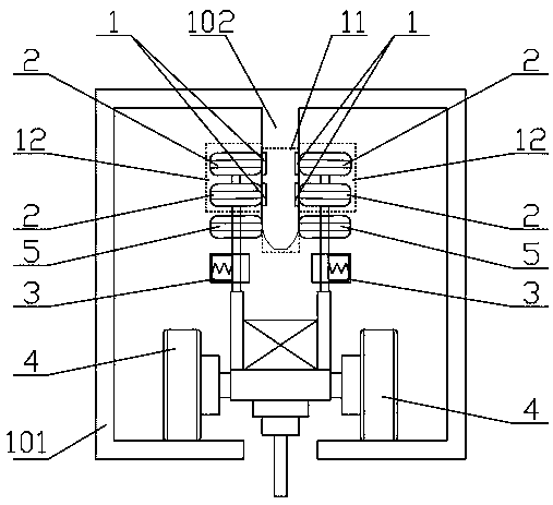
[0075] As preferred, such as figure 2 As shown, the first power supply device 11 includes at least two pairs of power supply contact rails 1, and at least one pair of power supply contact rails 1 are respectively positive and negative on the two opposite sides of the guide plate 102; One of...

Embodiment 2

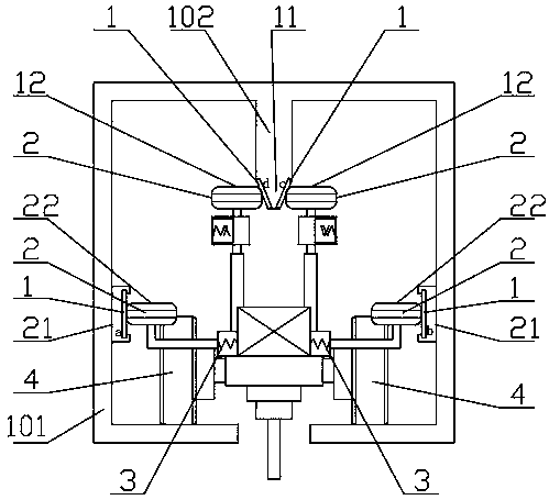
[0085] Embodiment 2, the second power supply device 21 is arranged along the entire guide rail 101 as the main power supply line. The first power supply device 11 is arranged at the switch as an auxiliary power supply line. It also includes a second power supply and power taking system, including a second power supply device 21, which is arranged on both sides of the inner wall of the guide rail 101 and arranged in parallel along the track of the guide rail 101; the second power taking device 22 is installed on the The two sides of the rail car 103; wherein, wherein, the second power taking device 22 can contact the second power supply device 21; the guide rail 101 has a switch section and a non-switch section; the first power supply The device 11 is arranged at least on the switch section of the guide plate 102 , and the second power supply device 21 is arranged at least on the switch section and the non-switch section of the guide plate 102 .

[0086] More specifically, the...

Embodiment 3

[0098] Embodiment 3, the first power supply device 11 and the second power supply device 21 are combined with each other, and both are arranged along the whole guide rail 101 . The second power supply and power taking system includes a second power supply device 21, which is arranged on both sides of the inner wall of the guide rail 101 and arranged in parallel along the track of the guide rail 101; the second power taking device 22 is installed on the track Both sides of the car 103; wherein, the second power-taking device 22 can contact the second power supply device 21 to obtain power;

[0099] Preferably, the first power supply device 11 includes a positive power supply contact rail 1 or a negative power supply contact rail 1; The power taking part 2; the second power supply device 21 includes the power supply contact rails 1 that are respectively arranged on both sides of the inner wall of the guide rail 101 and the polarity of the first power supply device 11 is opposite...


PUM


Abstract

The invention relates to a power supplying and taking system of a rail vehicle, which is used for a guide rail and a rail vehicle installed on the guide rail. The guide rail is provided with a guide plate including a power supply end for supplying electric power. A power take-off terminal installed on the rail car; a first power supply device arranged on the guide plate and arranged in parallel along the guide plate trajectory, and is electrically connected with the power supply terminal. The first power taking device is installed on the rail car and is connected with the power taking terminal, and control means for controlling contact or separation of the first power supply means and the first power take-off means, wherein the power take-off terminal contacts the first power supply devicethrough the first power take-off device to realize the connection between the power supply terminal and the power take-off terminal. Aiming at the problems of the existing products, the invention provides a power supply and power retrieval system of a rail vehicle which can maintain a stable power supply.

Description

technical field [0001] The invention relates to the technical field of guide rail transportation, in particular to a power supply and taking system for rail vehicles. Background technique [0002] Urban guide rail transportation is becoming more and more developed, with more and more applications. Monorail transportation is also a guide rail transportation mode that has emerged as the demand for urban traffic continues to increase. Compared with subways, it has more advantages in terms of construction period, cost, climbing ability, and turning radius, and it has also attracted more and more attention. Both the subway and the monorail need to be powered by electricity. [0003] At present, the common way of power supply and power supply is suitable for solving the problem of vehicle power supply in rail transit with switch mechanism, but it cannot solve the problem of continuous and stable power supply for vehicles in monorail traffic without switch mechanism when passing t...

Claims


Application Information

Patent Timeline
Patent Type & Authority Applications(China)
IPC IPC(8): B60L5/38B60M1/30B60M3/00
CPCB60L5/38B60L2200/26B60M1/30B60M3/00
Inventor 贾兴鲁
Owner 贾兴鲁
Why Eureka
Try Eureka