Municipal sewer fence jack
A sewer and jack technology, which is applied to waterway systems, water supply devices, drainage structures, etc., can solve the problem of difficulty in manually pulling a manhole cover, and achieve the effect of improving the convenience of operation.
- Summary
- Abstract
- Description
- Claims
- Application Information
AI Technical Summary
Problems solved by technology
Method used
Image

Examples
Embodiment 1
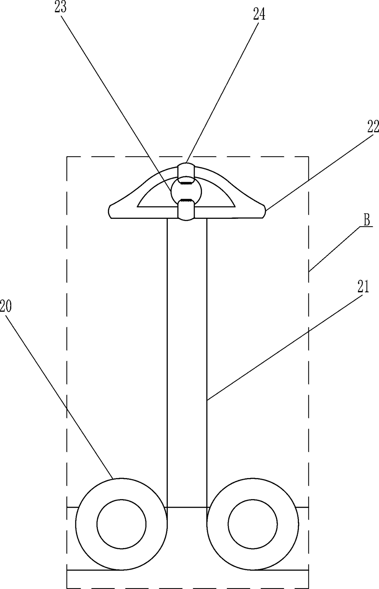
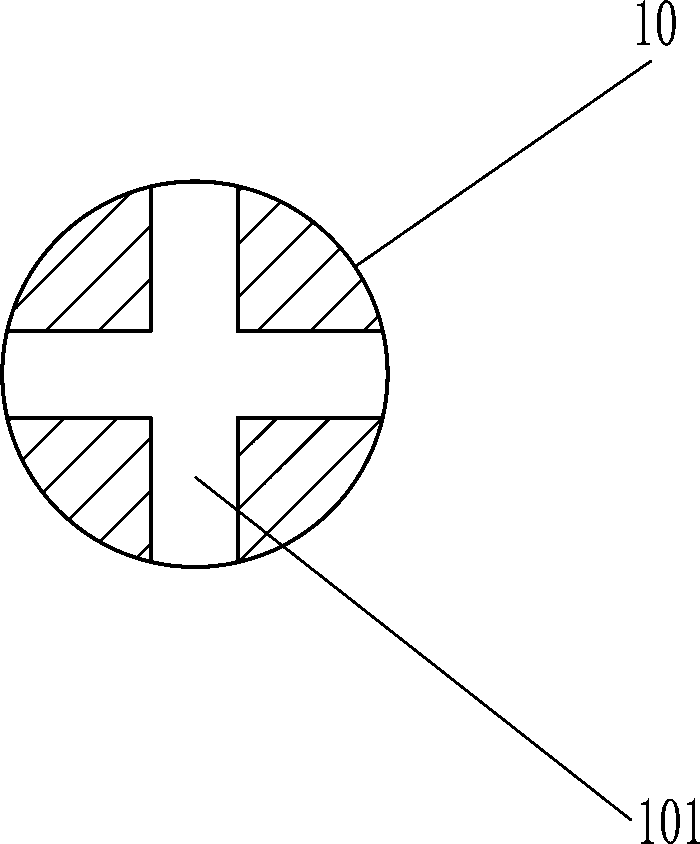
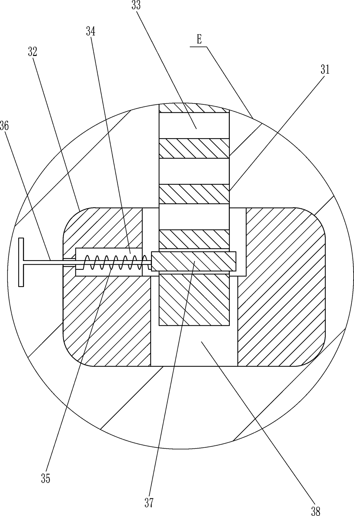
[0023] A municipal sewer barrier jack such as Figure 1-7 As shown, it includes a mounting column 1, a first slide rail 2, a first slider 3, a first block 4, a handle 5, a mounting block 6, a first spring 7, a lifting block 8, a first hook 10, a connection Block 11, second slide block 12, second slide rail 13, bearing housing 14, third slide rail 15, third slide block 16, second stop block 17 and insertion rod 18, the upper part of the front side of the mounting column 1 is connected with the first A slide rail 2, the first slide rail 2 is provided with a first slide block 3 slidingly, the bottom of the first slide rail 2 is connected with a first stopper 4, the right side of the first slide block 3 is connected with a handle 5, and the handle 5. The bottom of the installation block 6 is connected with the second slide rail 13 on the left side of the bottom of the installation block 6. The second slide rail 13 is slidably provided with the second slide block 12. The bottom of ...
Embodiment 2
[0025] A municipal sewer barrier jack such as Figure 1-7As shown, it includes a mounting column 1, a first slide rail 2, a first slider 3, a first block 4, a handle 5, a mounting block 6, a first spring 7, a lifting block 8, a first hook 10, a connection Block 11, second slide block 12, second slide rail 13, bearing housing 14, third slide rail 15, third slide block 16, second stop block 17 and insertion rod 18, the upper part of the front side of the mounting column 1 is connected with the first A slide rail 2, the first slide rail 2 is provided with a first slide block 3 slidingly, the bottom of the first slide rail 2 is connected with a first stopper 4, the right side of the first slide block 3 is connected with a handle 5, and the handle 5. The bottom of the installation block 6 is connected with the second slide rail 13 on the left side of the bottom of the installation block 6. The second slide rail 13 is slidably provided with the second slide block 12. The bottom of t...
Embodiment 3
[0028] A municipal sewer barrier jack such as Figure 1-7 As shown, it includes a mounting column 1, a first slide rail 2, a first slider 3, a first block 4, a handle 5, a mounting block 6, a first spring 7, a lifting block 8, a first hook 10, a connection Block 11, second slide block 12, second slide rail 13, bearing housing 14, third slide rail 15, third slide block 16, second stop block 17 and insertion rod 18, the upper part of the front side of the mounting column 1 is connected with the first A slide rail 2, the first slide rail 2 is provided with a first slide block 3 slidingly, the bottom of the first slide rail 2 is connected with a first stopper 4, the right side of the first slide block 3 is connected with a handle 5, and the handle 5. The bottom of the installation block 6 is connected with the second slide rail 13 on the left side of the bottom of the installation block 6. The second slide rail 13 is slidably provided with the second slide block 12. The bottom of ...
PUM
 Abstract
Description
Claims
Application Information
 - R&D
- Intellectual Property
- Life Sciences
- Materials
- Tech Scout
- Unparalleled Data Quality
- Higher Quality Content
- 60% Fewer Hallucinations
Browse by: Latest US Patents, China's latest patents, Technical Efficacy Thesaurus, Application Domain, Technology Topic, Popular Technical Reports.
© 2025 PatSnap. All rights reserved.Legal|Privacy policy|Modern Slavery Act Transparency Statement|Sitemap|About US| Contact US: help@patsnap.com