Water-cooled motor casing gas seal detecting device

A detection device and water-cooled motor technology, which is applied in the direction of measuring the increase and decrease rate of the fluid, and using liquid/vacuum degree to measure the liquid tightness, etc., can solve the problems of low detection efficiency, long time consumption, and heavy weight of the motor shell, etc., to achieve The effect of high detection efficiency, reduction of scrap rate and improvement of production efficiency

Active Publication Date: 2019-01-11
上海雷祥压铸有限公司
View PDF8 Cites 3 Cited by
  • Summary
  • Abstract
  • Description
  • Claims
  • Application Information

AI Technical Summary

Problems solved by technology

[0003] The leak detection method of the existing motor is to block the openings at both ends of the motor, and then pass air through one end of the phase to realize effective leak detection. In many cases, the motor casing is placed in the box for detection by manpower. The detection process requires high-intensity uninterrupted work by workers, which is time-consuming and low in detection efficiency.

Method used


Image

  • Water-cooled motor casing gas seal detecting device
  • Water-cooled motor casing gas seal detecting device
  • Water-cooled motor casing gas seal detecting device

Examples


Embodiment 1

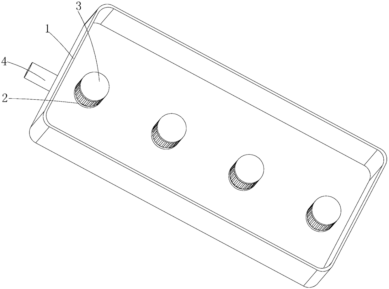
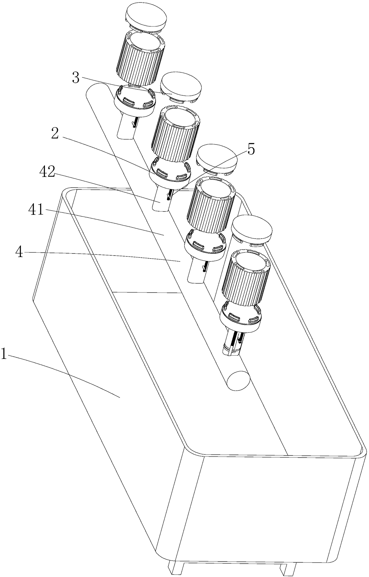
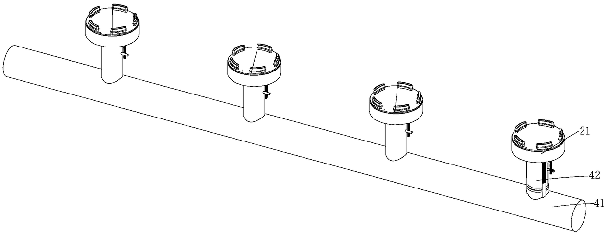
[0036] like Figure 1-10 As shown, a water-cooled motor casing air seal detection device includes a detection box 1, a first blocking part 2, a second blocking part 3, an air guide pipe 4 and an opening and closing structure 5, wherein the detection box 1 is made of metal box, the detection box 1 is filled with a detection liquid, the detection liquid can be water; the air guide pipeline 4 includes a main pipe 41 and a plurality of branch pipes 42, the main pipe 41 is a metal pipe, and the main pipe 41 is buried in the The bottom of the detection box 1, the branch pipe 42 is also a metal pipe, the branch pipe 42 is connected with the main pipe 41, the branch pipe 42 is perpendicular to the main pipe 41, and the branch pipe 42 is perpendicular to the bottom of the detection box 1 ; After the gas is passed into the main pipe 41, it will pass through each branch pipe 42 to the outside.

[0037] Further, the first blocking part 2 is connected to the lower part of the motor casing...

Embodiment 2

[0044] like Figure 11-13 As shown, the difference between this embodiment and Embodiment 1 is that this embodiment is additionally equipped with a place for putting the motor casing into the detection box 1 and / or removing the motor casing from the detection box 1. The material part, specifically: the discharge part 7 includes a fixed frame 70, a first clip 71, a second clip 72 and a first driver 73, the fixed frame 70 is a metal frame, and the second The clip 72 is a metal claw, and the upper part of the second clip 72 is connected with the fixed frame 70. The first clip 71 is also a metal claw, and the first clip 71 is connected to the first drive. 73, wherein the first driving member 73 is a cylinder, and the first driving member 73 is connected to the fixing frame 70, so when the motor casing needs to be fixed, the first driving member 73 drives the The first clamping piece 71 clamps the motor casing; at the same time, the discharging part 7 also includes a second drivin...


PUM


Abstract

The invention discloses a water-cooled motor casing gas seal detecting device, comprising a detecting box, an opening and closing structure, and a discharge member. The detecting box is used for holding a detecting liquid; the opening and closing structure is arranged on a branch pipe for opening the branch pipe to introduce gas into the motor casing when the branch pipe penetrates through a firstplugging member; the discharge member is used for putting the motor casing into the detecting box and / or taking the motor casing out of the detecting box. According to the water-cooled motor casing gas seal detecting device in the invention, the discharge member is placed so that the motor casing can be put into the detecting box and the motor casing is taken out of the detecting box. The processachieves automatic material taking and emptying without the need of manual operations; the automatic degree is high; a great number of manpower and material resources are saved; moreover, the detection efficiency that can be achieved is high due to automatic operations.

Description

technical field [0001] The invention belongs to the technical field of motor manufacturing, and in particular relates to an air seal detection device for a water-cooled motor shell. Background technique [0002] Water-cooled motors have been widely available in the market. By setting a cavity on the motor casing, and then through water circulation, the heat generated inside the motor is heat-exchanged. The cooling effect is good, and it can effectively protect the motor. The overall stability during the working process improves the service life of the motor; because the motor is powered internally, the water-cooled motor cannot leak water during the production process. Therefore, in the process of producing the motor, it is necessary to perform leak detection on the motor shell to ensure the use of the motor security. [0003] The leak detection method of the existing motor is to block the openings at both ends of the motor, and then pass air through one end of the phase to...

Claims


Application Information

Patent Timeline
Patent Type & Authority Applications(China)
IPC IPC(8): G01M3/26
CPCG01M3/26
Inventor 徐承迪
Owner 上海雷祥压铸有限公司
Why Eureka
Try Eureka