
A method for determining engine bearing shell parameters

A technology for parameter determination and engine shaft, which is applied in electrical digital data processing, computer-aided design, special data processing applications, etc., and can solve problems such as passive bearing optimization work and increased vehicle fuel consumption.

Active Publication Date: 2019-01-11
WEICHAI POWER CO LTD
View PDF6 Cites 2 Cited by
  • Summary
  • Abstract
  • Description
  • Claims
  • Application Information

AI Technical Summary

Problems solved by technology

During the working process of the engine, the friction loss work caused by the friction between the bearing bush and other adjacent parts will lead to an increase in the fuel consumption of the whole vehicle
[0003] In the existing technical scheme, the engine vehicle test can only be carried out after the prototype production is completed. If the bearing pad design does not meet the design target after the engine vehicle test is completed, the post-stage optimization of the bearing pad will be very passive.

Method used


Image

  • A method for determining engine bearing shell parameters
  • A method for determining engine bearing shell parameters

Examples


Embodiment Construction

[0034] The present invention will be further described in detail below in conjunction with the accompanying drawings and embodiments. It should be understood that the specific embodiments described here are only used to explain the present invention, but not to limit the present invention. In addition, it should be noted that, for the convenience of description, only some structures related to the present invention are shown in the drawings but not all structures.

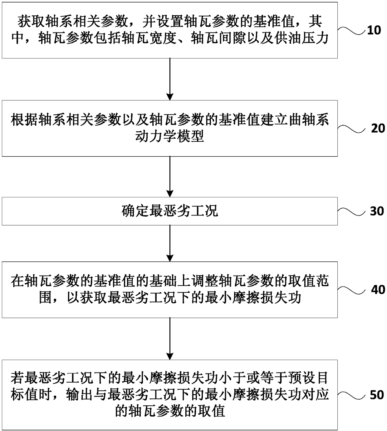
[0035] figure 1 It is a flow chart of a method for determining engine bearing pad parameters provided by an embodiment of the present invention. Optionally, refer to figure 1 , the method includes:

[0036] Step 10, obtaining related parameters of the shaft system, and setting a reference value of the bearing pad parameters, wherein the bearing pad parameters include the bearing pad width, the bearing pad clearance and the oil supply pressure.

[0037] Specifically, the shafting-related parameters are related t...


PUM


Abstract

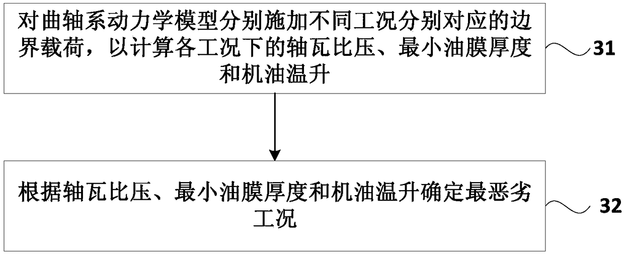
The invention discloses a method for determining engine bearing shell parameters. The method comprises the following steps of: acquiring shafting related parameters and setting a reference value of the bearing bush parameters; establishing the dynamic model of the crankshaft system according to the reference values of the shaft system parameters and the bearing bush parameters; determining the worst working conditions; adjusting the value range of the bearing bush parameter on the basis of the reference value of the bearing bush parameter to obtain the minimum friction loss work under the worst working condition; if the minimum friction loss work under the worst working condition is less than or equal to the preset target value, the value of the bushing parameter corresponding to the minimum friction loss work under the worst working condition is output. The embodiment adopts the simulation method to design the bearing bush parameters, so that the optimal bearing bush parameters can beobtained in the design process, and the situation that the bearing bush cannot meet the requirements can be avoided after the design of the whole machine is completed.

Description

technical field [0001] The embodiments of the present invention relate to the technical field of engine design, and in particular to a method for determining engine bearing parameters. Background technique [0002] The main bush of the engine is installed on the main bearing seat of the machine body, and its function is to reduce the frictional resistance of the journal and reduce the wear of the journal. When the engine is working, the bearing bush will bear the impact force transmitted by the moving parts, which not only wears out the adjacent parts, but also bears the maximum load. During the working process of the engine, the friction loss work caused by the friction between the bearing bush and other adjacent parts will lead to an increase in the fuel consumption of the whole vehicle. [0003] In the existing technical scheme, the engine vehicle test can only be carried out after the prototype production is completed. If the bearing pad design does not meet the design ...

Claims


Application Information

Patent Timeline
Patent Type & Authority Applications(China)
IPC IPC(8): G06F17/50
CPCG06F30/17G06F2119/06Y02T90/00
Inventor 占兴潮胡益聪王晓艳钱妍周杨
Owner WEICHAI POWER CO LTD
Learn More