
A wafer detecting method

A detection method and wafer technology, which can be used in semiconductor/solid-state device testing/measurement, electrical components, semiconductor/solid-state device manufacturing, etc., and can solve problems such as deficiencies

Active Publication Date: 2019-01-11
SUZHOU JINGLAI OPTO CO LTD
View PDF6 Cites 2 Cited by
  • Summary
  • Abstract
  • Description
  • Claims
  • Application Information

AI Technical Summary

Problems solved by technology

[0004] At present, the technology of ultra-micro display and near-eye large-screen equipment with wafer as the core is relatively new, and the wafer manufacturing process is still in the stage of exploration and trial. Therefore, there may be some defects in the wafer manufacturing process. The adjustment of the manufacturing process in the wafer requires defect inspection on the wafer. However, the existing market is still lacking in wafer inspection methods

Method used


Image

  • A wafer detecting method
  • A wafer detecting method
  • A wafer detecting method

Examples


Embodiment Construction

[0039] The technical solutions of the present invention will be further described below in conjunction with the accompanying drawings and through specific implementation methods.

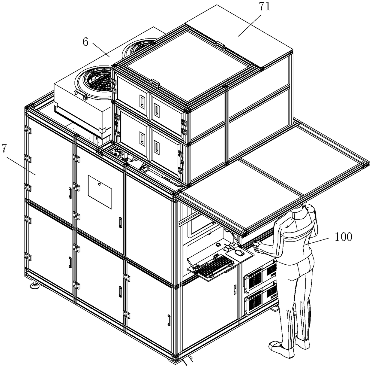
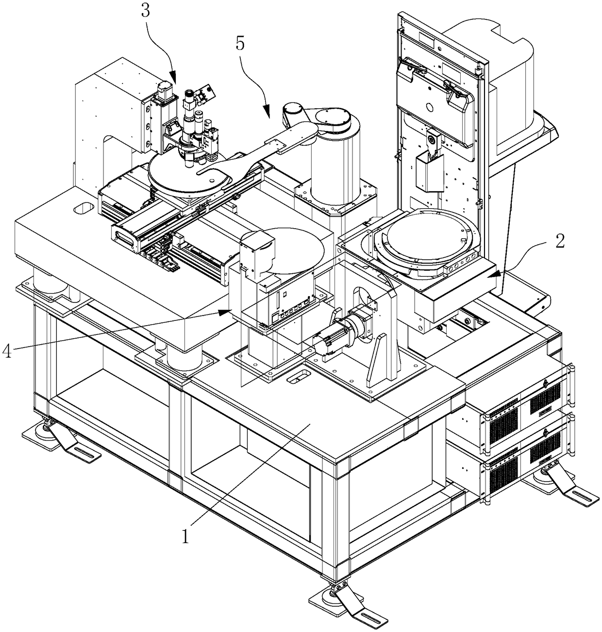
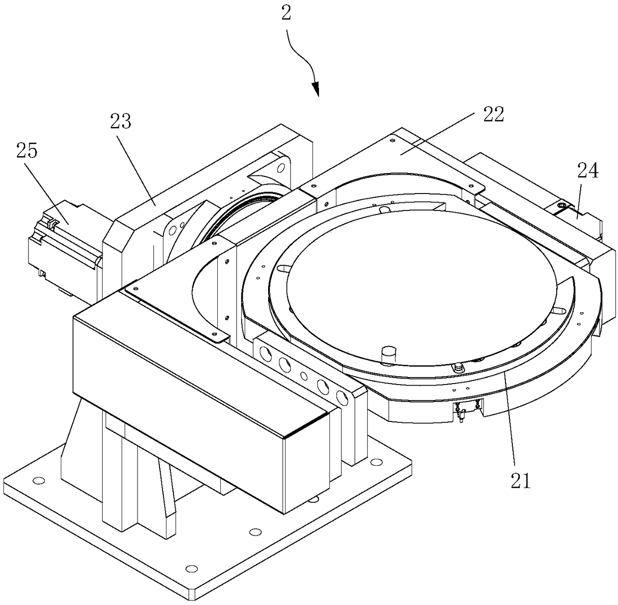
[0040] This embodiment discloses a wafer detection device, such as figure 1 and 2 As shown, the wafer detection equipment includes a working platform 1, on which at least a macroscopic detection station 2 and a microscopic detection station 3 are arranged, and a handling device 5 is also arranged on the working platform 1, and the handling device 5 can The wafer to be inspected is transported to the macro inspection station 2 and the micro inspection station 3. By setting the macro inspection station 2 and the micro inspection station 3 on the wafer inspection equipment, the wafer can be inspected macroscopically and microscopically. Among them, the macro inspection station 2 mainly observes the defects visible to the naked eye on the wafer; the microscopic inspection Station 3 mainly uses the mic...


PUM


Abstract

The invention belongs to the technical field of electronic product processing and production, and discloses a wafer detecting method. The method includes S1, providing a wafer detection device with atleast macroscopic detection station and microscopic detection station, providing a wafer detection device with at least microscopic detection station and a wafer detection device with at least microscopic detection station; S2, carry that wafer to be tested to the macroscopic detection station and / or the microscopic detection station, and carrying out macroscopic detection and / or microscopic detection on the wafer to be tested; S3, removing the detected wafer from the wafer detection apparatus. The wafer detection method of the present invention can perform macroscopic and microscopic detection on a wafer by providing a wafer detection device with a macroscopic detection station and a microscopic detection station, wherein the macroscopic detection station mainly observes defects visibleto the naked eye on the wafer. The microscopic inspection station mainly observes the defects on the wafer which can not be observed by the naked eye through the microscope equipment, so that the defects caused by the processing technology can be detected and analyzed comprehensively so as to improve the wafer in time.

Description

technical field [0001] The invention relates to the technical field of electronic product processing and production, in particular to a wafer detection method. Background technique [0002] Wafer microdisplay devices are different from conventional AMOLED devices that use amorphous silicon, microcrystalline silicon or low-temperature polycrystalline silicon thin film transistors as the backplane. [0003] Wafer microdisplays have a broad market application space, especially suitable for helmet-mounted displays, stereoscopic display mirrors, and eye displays, and can be used for portable computers, wireless Internet browsers, portable DVDs, game platforms, and wearable computers. Mobile information products provide high-quality video display, and even when combined with mobile communication networks and satellite positioning systems, accurate image information can be obtained anywhere and at any time, so that it can be used in national defense, aviation, aerospace and even in...

Claims


Application Information

Patent Timeline
Patent Type & Authority Applications(China)
IPC IPC(8): H01L21/66H01L21/67
CPCH01L21/67259H01L22/26
Inventor 朱志飞舒文宾杨慎东郭连俊
Owner SUZHOU JINGLAI OPTO CO LTD
Learn More