Ship truss web structure and ship structure

A web and girder technology, applied in the field of ship girder web structure and ship structure, can solve the problems of many stress concentration points in through holes, affecting the strength and safety of girder web structure, and many openings, etc., to achieve Reduce fatigue sources, improve structural fatigue resistance, and reduce the effect of stress concentration points

Active Publication Date: 2019-01-15
GUANGZHOU SHIPYARD INTERNATIONAL LTD
View PDF8 Cites 4 Cited by
  • Summary
  • Abstract
  • Description
  • Claims
  • Application Information

AI Technical Summary

Problems solved by technology

[0005] The purpose of the present invention is to provide a ship girder web structure and a ship structure to solve the problem that the existing girder web structure has many openings, and the stress concentration points caused by the small size of the through hole affect the girder web structure. Technical issues of strength and safety of web structures

Method used


Image

  • Ship truss web structure and ship structure
  • Ship truss web structure and ship structure
  • Ship truss web structure and ship structure

Examples


Embodiment 1

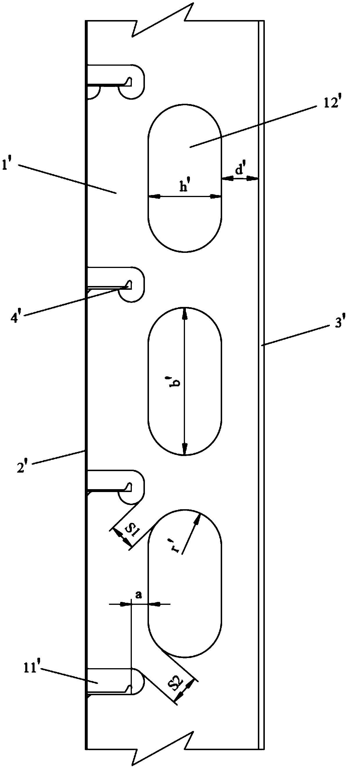
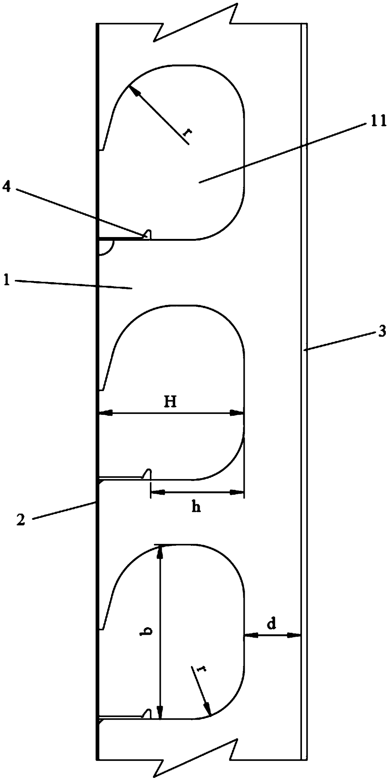
[0027] This embodiment provides a ship girder web structure, which is suitable for ship superstructure structures, especially passenger ships, ro-ro passenger ships and ro-ro ships. The design is adopted at a position above the center of gravity of the ship, which is beneficial to reduce the center of gravity of the empty ship. like image 3 As shown, the ship girder web structure includes a web 1 and a frame 4. One side of the web 1 is connected to the belt plate 2, and the other side is connected to the girder panel 3. A hole 11 , the aggregate 4 is arranged perpendicular to the web 1 through the through hole 11 , one end of the aggregate 4 is in contact with the belt plate 2 , and one side of the aggregate 4 is in contact with the inner wall of the through hole 11 . The ship girder web structure of this embodiment makes the lightening hole or outfitting hole and the through hole share the same through hole 11, which can make the total opening without affecting the strength ...

Embodiment 2

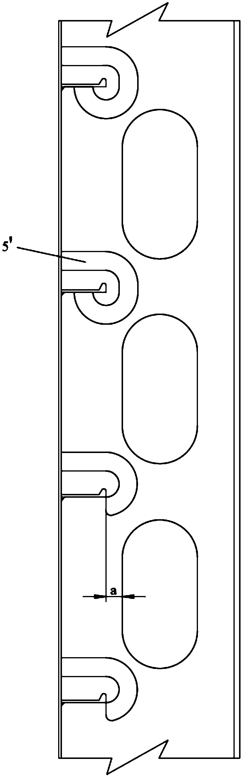
[0031] The difference from Embodiment 1 is that, as Figure 4 As shown, one side of the through hole 11 starts from the intersection of the belt plate 2 and the aggregate 4, fits the aggregate 4 and opens along the width direction of the web 1, and returns to the aggregate 4 after passing through several straight lines and arcs. , and then return to the belt plate 2 along the aggregate 4. This structure makes the shape of the hole where the frame 4 passes fits with the structure of the frame 4, and the connection is more stable, and without increasing the stress concentration point, the area of ​​some openings is appropriately reduced, and the web of the girder is improved. The strength of the plate structure is increased, but at the same time the weight reduction effect is slightly reduced.

[0032] The present invention also provides a ship structure, including the ship girder web structure provided in Embodiment 1 or Embodiment 2.

[0033]The total opening area of ​​the g...


PUM


Abstract

The invention discloses a ship truss web structure and a ship structure, belonging to the technical field of ships. The ship truss web structure comprises a web plate and a bone material, wherein oneside of the web plate is a belt plate and the other side is a truss panel; a through hole is arranged on the web plate; the bone material is perpendicular to the web plate and passes through the through hole; one end of the bone material is in contact with the belt plate; and one side of the bone material is in contact with the inner wall of the through hole. The ship truss web structure of the invention enables the lightening hole or the outfitting hole and the through hole to share the same through hole, and under the condition of not affecting the strength of the web and not increasing thestress concentration point, the total opening area is larger, the weight reduction effect of the web structure is more obvious, and the weight reduction effect of the web structure is beneficial to reducing the center of gravity of the empty ship. Available openings are larger in size, especially in height, and can be outfitted with more and larger pipes or cables, thus reducing the number of openings, reducing the stress concentration point, reducing the fatigue source, and improving the anti-fatigue capacity of the structure.

Description

technical field [0001] The invention relates to the technical field of ships, in particular to a ship girder web structure and a ship structure. Background technique [0002] Since the girder web 1' used in ships needs to reduce weight and pass through various outfittings (such as pipes or cables, etc.), various holes need to be provided to meet the requirements. like figure 1 and figure 2 As shown, the existing girder web 1' is usually provided with a through hole 11' and an outfitting hole 12' respectively. Generally, the through hole 11' is relatively small, and one side of the through hole 11' is closely connected to the passing frame 4'. The other side of the through hole 11' is generally no more than 100 mm away from the frame 4', one end of the through hole 11' is in contact with the strip plate 2', and the other end is extended to the inside of the web 1' of the girder. The height is generally 4' of the aggregate plus 35 mm. [0003] At the same time, when openi...

Claims


Application Information

Patent Timeline
IPC IPC(8): B63B15/00
CPCB63B15/00
Inventor 王亮
Owner GUANGZHOU SHIPYARD INTERNATIONAL LTD
Why Eureka
Try Eureka