Al technical title is built by PatSnap Al team. It summarizes the technical point description of the patent document.
A technology of lifting conveying and conveying strips, which is applied in the direction of conveyor objects, transportation and packaging, etc., which can solve the problems of damaged feeding, inconvenient users, and easy over-heading, etc.
Inactive Publication Date: 2019-01-15
黄小翠
View PDF1 Cites 2 Cited by
Summary
Abstract
Description
Claims
Application Information
AI Technical Summary
This helps you quickly interpret patents by identifying the three key elements:
Problems solved by technology
Method used
Benefits of technology
Problems solved by technology
[0004] In view of the deficiencies in the existing technology, the purpose of the present invention is to provide a lifting and conveying mechanism to solve the problem that the existing technology is easy to rise too much, causing the material to be damaged due to the drop of the height difference, which brings great inconvenience to the user
Method used
Image
Click on the blue label to locate the original text in one second.
Reading with bidirectional positioning of images and text.
Examples
Embodiment Construction
[0022] In order to make the technical means, creative features, goals and effects achieved by the present invention easy to understand, the present invention will be further described below in conjunction with specific embodiments.
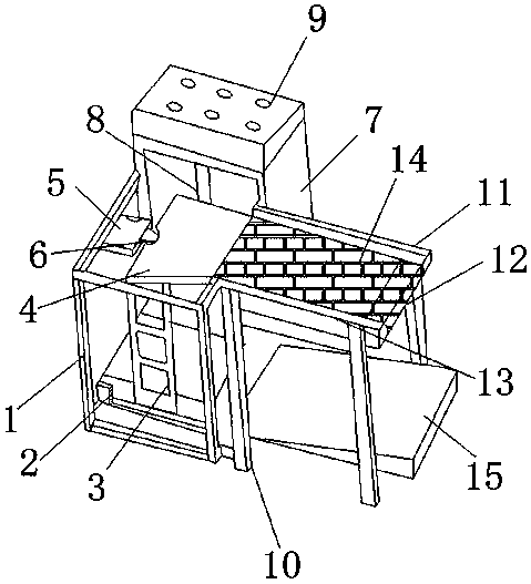
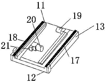
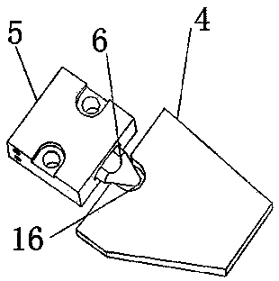
[0023] see figure 1 , figure 2 , image 3 and Figure 4 , the present invention provides a lifting and conveying mechanism: including a first frame 1, a first telescopic frame 3, a feeding plate 4, a reserve power supply 7, a second telescopic frame 8, a controller 9, a second frame 10, and a first rod 11 , support plate 12, second frame bar 13, conveyor belt 14, feed hopper 15, first conveyor bar 17, second conveyor bar 18, right motor 19, groove 16, left motor 20, also includes catapult 2, positioning plate 5. Bar 6, electromagnetic push rod 21, the bottom of the first frame 1 is equipped with a catapult 2, the top of the catapult 2 is movably connected to the first telescopic frame 3, and the top of the first telescopic frame 3 is fixedly c...
PUM
Abstract
The invention discloses a lifting conveying mechanism. The lifting conveying mechanism structurally comprises a first frame, a first expansion bracket, a feeding plate, a reserve power supply, a second expansion bracket, a controller, a second frame, a first frame bar, a supporting plate, a second frame bar, a conveying belt, a feeding hopper, a first conveying strip, a second conveying strip, a right motor, a groove, a left motor, an ejector, a positioning plate, a clamping bar and an electromagnetic push rod. The ejector is installed at the bottom of the first frame, and the first expansionbracket is movably connected with the top of the ejector. According to the lifting conveying mechanism, the clamping bar on the positioning plate and the groove in the feeding plate are arranged, andwhen the feeding plate is raised by the expansion brackets, the height of the feeding plate can be fixed as the diameter of the middle of the clamping bar is larger than that of the groove so that a product on the feeding plate can be moved to the conveying belt to be conveyed, and the phenomenon that in the prior art, excessive raising is likely to happen, and consequently conveyed materials falland are damaged due to a height difference is avoided.
Description
technical field [0001] The invention relates to a lifting conveying mechanism, which belongs to the field of conveying mechanisms. Background technique [0002] The conveyor belt is a tool for product delivery. With the development of mechanical and electrical industries, the conveyor belt has been continuously improved and has become an important part of the material transmission automation system. With the rapid development of science and technology, the current conveying mechanism does not have the lifting and feeding mechanism, which causes time-consuming and labor-intensive work and brings great inconvenience to users. [0003] The prior art discloses a lifting and conveying mechanism with the application number of 201620081747.9, which includes a conveyor belt base, a motor, a motor reducer, a conveyor belt adjustment bracket, and a transmission control device. The motor and the motor are provided on one side of the conveyor belt base. Reducer, the two ends of the ...
Claims
Application Information
Patent Timeline
Application Date:The date an application was filed.
Publication Date:The date a patent or application was officially published.
First Publication Date:The earliest publication date of a patent with the same application number.
Issue Date:Publication date of the patent grant document.
PCT Entry Date:The Entry date of PCT National Phase.
Estimated Expiry Date:The statutory expiry date of a patent right according to the Patent Law, and it is the longest term of protection that the patent right can achieve without the termination of the patent right due to other reasons(Term extension factor has been taken into account ).
Invalid Date:Actual expiry date is based on effective date or publication date of legal transaction data of invalid patent.