

Optical coded electronic encryption lock
A technology of optical coding and encryption lock, which is applied in the field of smart devices, can solve problems such as low encryption level, security loopholes, failures, etc., and achieve the effect of improving security and enhancing the security level
- Summary
- Abstract
- Description
- Claims
- Application Information
AI Technical Summary
Problems solved by technology
Method used
Image

Examples
Embodiment Construction
[0014] Embodiments of the present invention will be further described below in conjunction with the accompanying drawings.
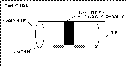
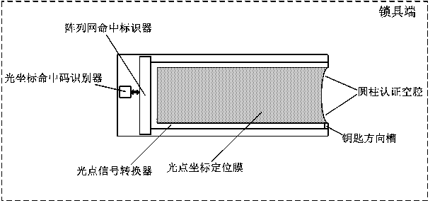
[0015] Please see attached figure 1 As shown, the optically encoded electronic encryption lock includes a lock end 1 and an optically encoded key end 2. The lock end 1 includes an optical point coordinate positioning film 3, an optical point signal converter 4, an array network hit marker 5, and an optical coordinate hit Code recognizer 6, key direction groove 7, described optical coding key end 2 comprises optical code emitting cylindrical rod 8, starting lap 9, described optical point coordinate positioning film 3 is connected to optical point signal converter 4, Described optical point signal converter 4 is connected to array net hit marker 5, and described array net hit marker 5 is connected to optical coordinate hit code recognizer 6, and described optical code emits cylindrical rod 8 and starts to overlap Device 9 is connected.
[0016] The optic...
PUM
 Abstract
Description
Claims
Application Information