Concentrated winding permanent magnet motor

A permanent magnet motor and concentrated winding technology, which is applied to the shape/style/structure of the winding conductor, the static parts of the magnetic circuit, the shape/style/structure of the magnetic circuit, etc., can solve the problems of limiting the rated output power of the motor, and achieve output Increased power, reduced manufacturing material costs, and expanded application range

Active Publication Date: 2019-03-08
SHANGHAI ZHONGCHEN ELECTRONICS TECH
View PDF4 Cites 0 Cited by
  • Summary
  • Abstract
  • Description
  • Claims
  • Application Information

AI Technical Summary

Problems solved by technology

The internal loss value of the motor determines the temperature rise of the motor, which also limits the rated output power of the motor

Method used


Image

  • Concentrated winding permanent magnet motor
  • Concentrated winding permanent magnet motor
  • Concentrated winding permanent magnet motor

Examples


Embodiment 1

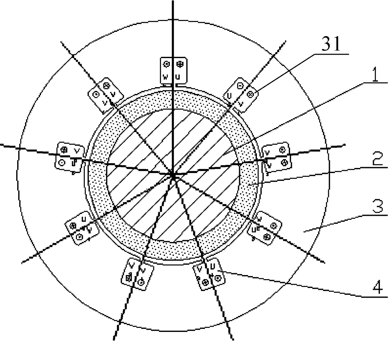
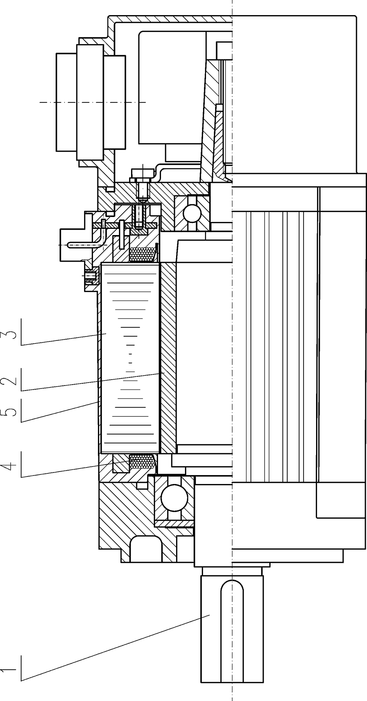
[0036] A concentrated winding permanent magnet motor, including a motor shaft 1 as a motor rotor yoke, a radiation ring 2, a motor stator core 3 and a motor armature winding 4, such as Figure 1 to Figure 5 As shown, the specific structure is:

[0037] The radiation ring 2 is hooped outside the motor shaft 1, and the motor stator core 3 is set outside the radiation ring 2. There is a gap between the motor stator core 3 and the radiation ring 2. The motor shaft 1, the radiation ring 2 and the motor stator core 3 The central axis of the motor stator core 3 coincides with the inner side wall of the motor stator core 3. There are winding slots 31 parallel to the central axis of the motor stator core 3. The number of winding slots 31 is 9. The winding slots 31 are along the section of the inner hole of the motor stator core 3. Evenly distributed in the circumferential direction, that is, 9 winding slots 31 divide the section of the inner hole of the motor stator core 3 into 9 secti...

Embodiment 2

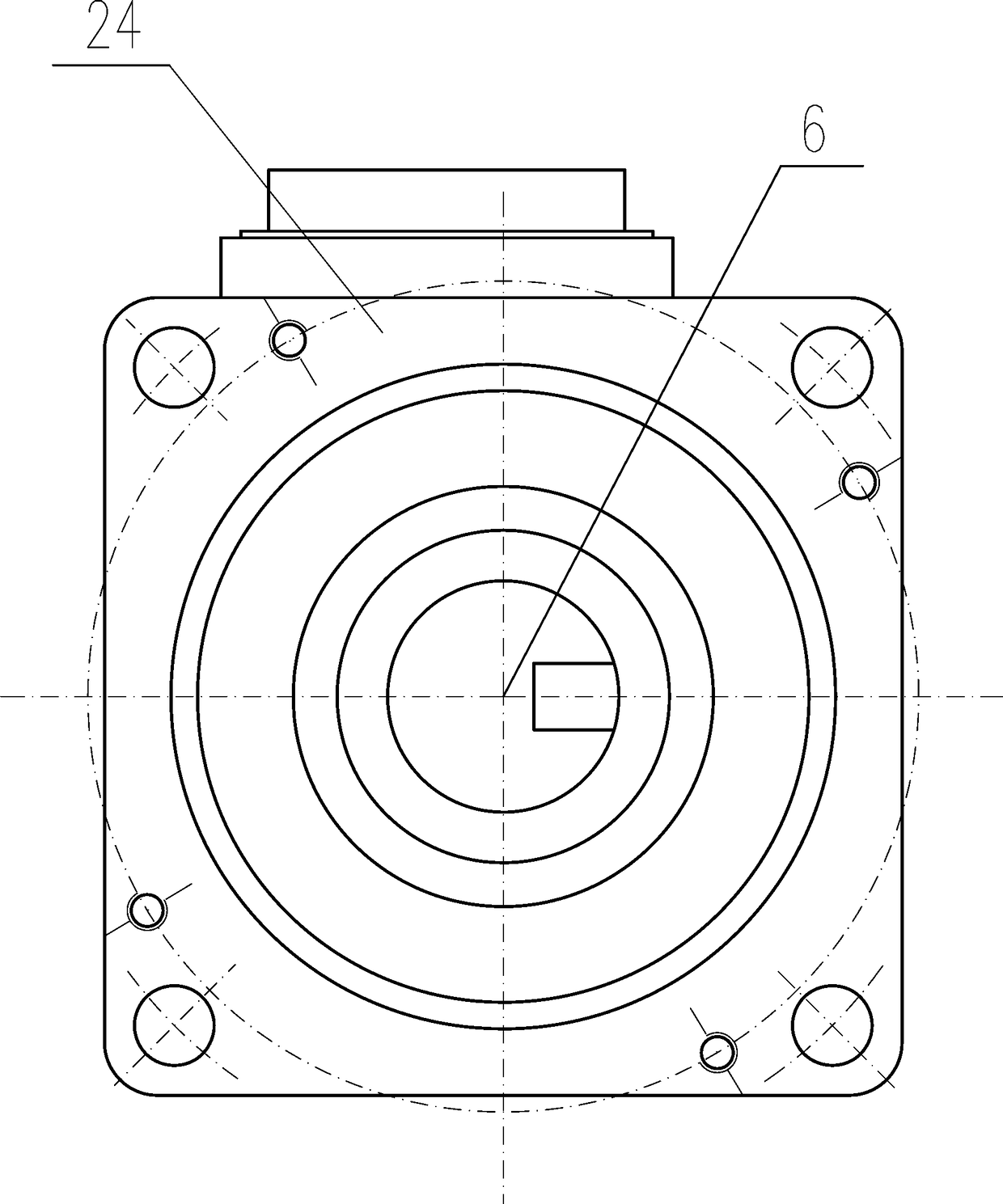
[0056] A concentrated winding permanent magnet motor, including a motor shaft 1 as a motor rotor yoke, a radiation ring 2, a motor stator core 3 and a motor armature winding 4, and also includes a sensor 7, the sensor 7 in this embodiment uses incremental coding device, such as Figure 6 As shown, the sensor 7 is arranged in the casing 5, and the rotating shaft of the sensor 7 is fixedly connected with the motor shaft 1 in a manner that the central axis coincides, and the outer side of the sensor 7 is covered by an outer cover plate 71. Other structures are all the same as in Embodiment 1.

[0057] When this embodiment is used, when the motor is running, some operating parameters of the motor can be obtained through the signal output by the signal line of the incremental encoder as the sensor 7 . Other usage methods are all the same as embodiment 1.

Embodiment 3

[0059] A concentrated winding permanent magnet motor, including a motor shaft 1 as a motor rotor yoke, a radiation ring 2, a motor stator core 3 and a motor armature winding 4, and also includes a sensor 7, the sensor 7 in this embodiment uses an absolute value type code Sensor, sensor 7 is located in the casing 5, the rotating shaft of sensor 7 and motor shaft 1 are fixedly connected with the mode that central axis overlaps, and the outside of sensor 7 is covered with outer cover plate 71. Other structures are all the same as in Embodiment 1.

[0060] When this embodiment is used, when the motor is running, some operating parameters of the motor can be obtained through the signal output by the signal line of the incremental encoder as the sensor 7 . Other usage methods are all the same as embodiment 1.


PUM


Abstract

The invention relates to the field of permanent magnet containing synchronous motors, and particularly relates to a concentrated winding permanent magnet motor. The concentrated winding permanent magnet motor comprises a motor shaft (1), a radiation ring (2), a motor stator core (3), and motor armature windings (4). The concentrated winding permanent magnet motor is characterized in that the radiation ring (2) hoops the motor shaft (1), the motor stator core (3) sleeves the radiation ring (2), a gap is left between the motor stator core (3) and the radiation ring (2), and a wire is wound inside winding slots (31) turn by turn to form nine motor armature windings (4). The concentrated winding permanent magnet motor has the advantages of high rated output power, high degree of automation in the production process, high production efficiency, and wide range of application.

Description

technical field [0001] The invention relates to the field of synchronous motors with permanent magnets, in particular to a concentrated winding permanent magnet motor. Background technique [0002] The permanent magnet motor is a three-phase synchronous motor, including the stator, the rotor made of permanent magnet steel and other components. The permanent magnet motor has no electric excitation winding, and has the advantages of simple structure, small size, light weight, low loss, high efficiency, and high power. It has the advantages of high factor and is mainly used in high-performance servo drive systems that require fast response, wide speed range and accurate positioning. The design of the permanent magnet motor follows the design method of the conventional three-phase synchronous motor, and adopts a multi-slot distributed winding design in which the number of slots per pole and each phase q is an integer, so as to reduce the additional eddy current generated by the ...

Claims


Application Information

Patent Timeline
Patent Type & Authority Patents(China)
IPC IPC(8): H02K1/16H02K3/28
Inventor 王海彬周绍宗吴春年
Owner SHANGHAI ZHONGCHEN ELECTRONICS TECH
Why Eureka
Try Eureka