a double lumen tube
A lumen tube and ventilation cavity technology, applied in the field of medical hygiene materials, can solve the problems of poor intubation accuracy, convenience and adjustability, glottis and tracheal tissue damage, etc.
- Summary
- Abstract
- Description
- Claims
- Application Information
AI Technical Summary
Problems solved by technology
Method used
Image
Examples
Embodiment 1
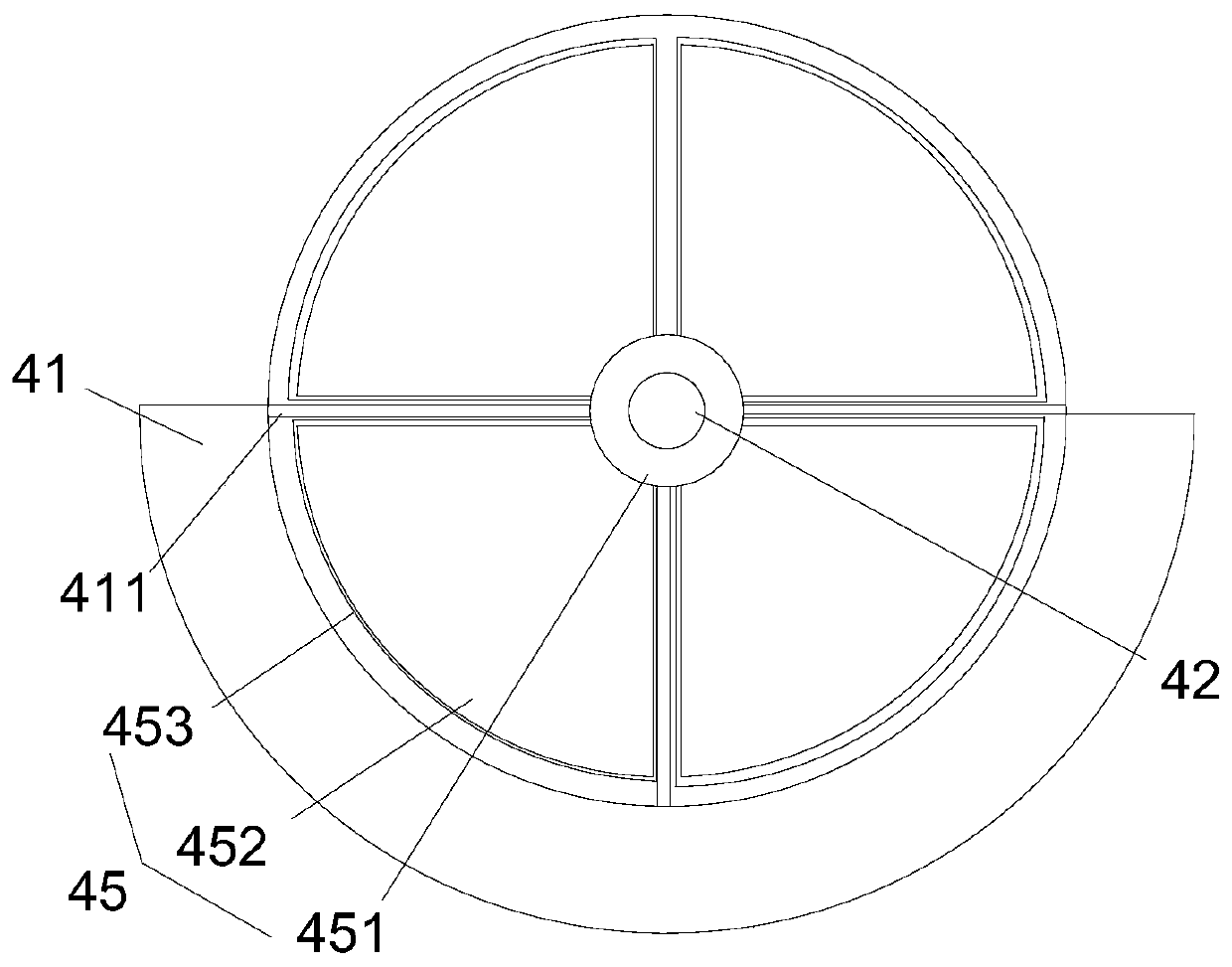
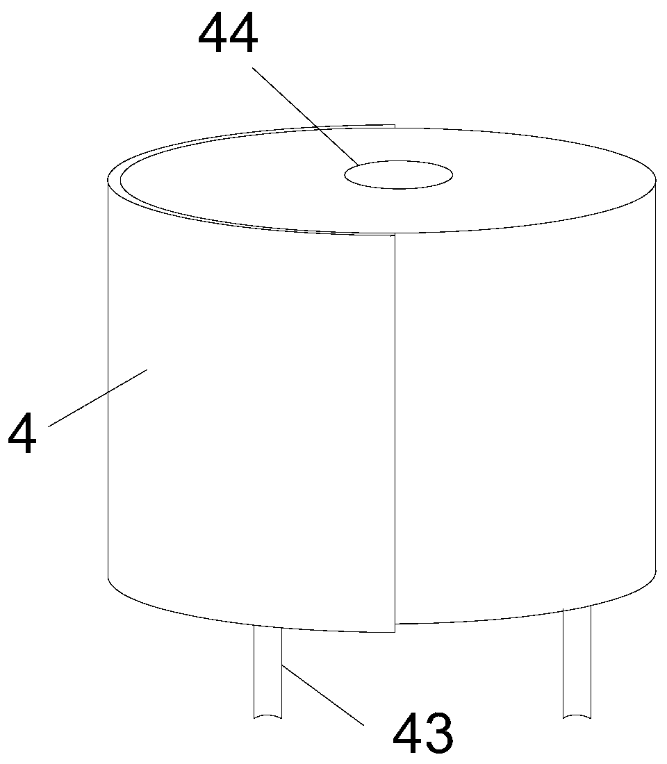
[0077] Such as figure 1 As shown, the present invention provides a double-lumen tube, including an endotracheal tube 1, a partition plate 12 arranged along the length direction of the endotracheal tube 1 so that the inner cavity of the endotracheal tube 1 is divided into two independent ventilation chambers 11, The endotracheal tube 2 is inserted into the two ventilation chambers 11 from the bottom of the endotracheal tube 1, and the ventilation device 3 and the adjustment device 4 are arranged on the top of the endotracheal tube 1 from bottom to top; the ventilation device 3 is in communication with the air source 100 Oxygen is supplied to the two ventilation chambers 11; the ventilation device 3 is fixedly connected to the partition plate 12; the regulating device 4 is fixedly connected to the endotracheal tube 2;
[0078] In Embodiment 1, the endotracheal tube 2 can rotate axially relative to the endotracheal tube 1 through the ventilation device 3 ; When the endotracheal ...
Embodiment 2
[0096] The difference between Embodiment 2 and Embodiment 1 is that at least one of the two endotracheal tubes 2 can rotate relative to its axis through the adjustment device 4 , and the endotracheal tube 2 can be stretched relative to the endotracheal tube 1 through the adjustment device 4 . In this embodiment, the ventilation device 3 is fixedly connected to the fixed seat 13, the ventilation device 3 cannot rotate relative to the endotracheal tube 1, so the partition plate 12 cannot rotate, and the stretching and rotation of the endotracheal tube 2 are all through the adjustment device 4 realized. The difference between the technical solution of this embodiment 2 and the embodiment 1 is that the ventilation device 3 is fixedly connected to the fixed seat 13 , and the adjustment device 4 is connected to the top of the ventilation device 3 by rotation.
[0097] As an optional embodiment, the number of adjustment devices 4 is two, and the two adjustment devices 4 are rotated s...
Embodiment 3
[0100] The difference between Embodiment 3 and Embodiment 2 is that the endotracheal tube 2 can rotate relative to the axis of the endotracheal tube 1 through the ventilation device 3, and at least one of the two endotracheal tubes 2 can rotate relative to its axis through the adjustment device 4 , the endotracheal tube 2 can be stretched relative to the endotracheal tube 1 through the adjustment device 4 .
[0101] The structure and connection relationship between the ventilation device 3 and the endotracheal tube 1 in this embodiment 3 are the same as the scheme in embodiment 1, and the connection and structural relationship between the adjustment device 4 and the ventilation device 3 are the same as the scheme in embodiment 2 same.
[0102] The present invention also provides a double-lumen tube intubation method, comprising the following steps:
[0103] Step A: Prepare for surgery, prepare corresponding surgical tools before intubation, and adjust the bending direction of...
PUM
 Abstract
Description
Claims
Application Information
 - R&D
- Intellectual Property
- Life Sciences
- Materials
- Tech Scout
- Unparalleled Data Quality
- Higher Quality Content
- 60% Fewer Hallucinations
Browse by: Latest US Patents, China's latest patents, Technical Efficacy Thesaurus, Application Domain, Technology Topic, Popular Technical Reports.
© 2025 PatSnap. All rights reserved.Legal|Privacy policy|Modern Slavery Act Transparency Statement|Sitemap|About US| Contact US: help@patsnap.com


