Chemical filtration device and working method thereof
The technology of a filtering device and a working method, which is applied in the field of filtering devices, can solve the problems such as the dumping of the filtering bottle body, the high center of gravity, and the dumping of the liquid.
- Summary
- Abstract
- Description
- Claims
- Application Information
AI Technical Summary
Problems solved by technology
Method used
Image
Examples
no. 1 example
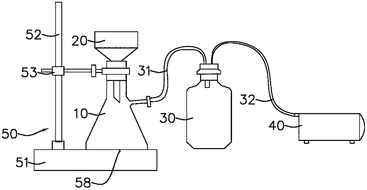
[0041] Such as Figures 2 to 4 As shown, the chemical filter device of this embodiment includes a filter bottle body 10 , a filter funnel 20 , a buffer bottle 30 , a vacuum pump 40 and a fixing device 50 .
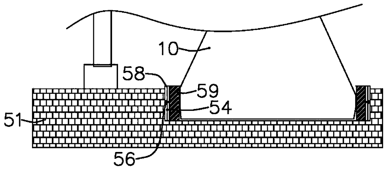
[0042]The filter funnel 20 is arranged on the filter bottle body 10 . The buffer bottle 30 is connected to the filter bottle body 10 through a first conduit 31 . The vacuum pump 40 is connected with the filter bottle body 10 through the second conduit 32 . The fixing device 50 has a base plate 51, a support rod 52 and a clamping member 53, the bottom of the support rod 52 is arranged on the base plate 51, the clamping member 53 is fixed on the support rod 52, and one end of the clamping member 53 clamps and fixes the filter bottle body 10 for the neck. The concrete structure of clamping part 53 is existing structure, and it can adopt the iron clip structure on the iron frame platform, and clamping part 53 can be adjusted correspondingly according to the neck size of fil...
no. 2 example
[0050] This embodiment is basically the same as the above-mentioned first embodiment, and only the differences will be described in detail below.
[0051] Such as Figure 5-8 , Figure 11 As shown, the elastic ring body 59 of this embodiment includes a first ring body 61, a second ring body 62 and a third ring body 63 from the inside to the outside, and the first ring body 61 has multiple sets of first internal threads in the shape of half The hole 64, the second annular body 62 has multiple groups of half-shaped second internally threaded holes 65, the first internally threaded hole 64 cooperates with the second internally threaded hole 65 to form a threaded hole, and a bolt 66 is arranged in the threaded hole. The structure of the first internally threaded hole 64 and the second internally threaded hole 65 is specifically a groove body with a semicircular cross-section. After the two holes are arranged oppositely, a complete threaded hole is formed, and the first internally...
no. 3 example
[0055] This embodiment is basically the same as the above-mentioned first embodiment, and only the differences will be described in detail below.
[0056] Such as Figure 9 As shown, the bottom plate 51 of the present embodiment is also provided with a support body 70, the support body 70 is provided with a metering barrel 71, the metering barrel 71 is used to load the liquid to be filtered, and the metering barrel 71 is provided with a stirring rod body 72. Barrel 71 is connected with filter funnel 20 through conduit 73, and the bottom of metering barrel 71 is provided with discharge port 74, and discharge port 74 is provided with electromagnetic valve 76, and conduit 73 is provided with flowmeter 75, controller and flowmeter 75, electromagnetic valve 76 connection;
[0057] The working method includes the following steps:
[0058] Put the liquid to be filtered into the metering barrel 71, control the flow of liquid flowing out of the discharge port 74 through the electroma...
PUM
 Abstract
Description
Claims
Application Information
 - R&D
- Intellectual Property
- Life Sciences
- Materials
- Tech Scout
- Unparalleled Data Quality
- Higher Quality Content
- 60% Fewer Hallucinations
Browse by: Latest US Patents, China's latest patents, Technical Efficacy Thesaurus, Application Domain, Technology Topic, Popular Technical Reports.
© 2025 PatSnap. All rights reserved.Legal|Privacy policy|Modern Slavery Act Transparency Statement|Sitemap|About US| Contact US: help@patsnap.com


