A crankshaft polishing support device with self-cleaning function
What is Al technical title?
Al technical title is built by PatSnap Al team. It summarizes the technical point description of the patent document.
A support device and crankshaft technology, applied in grinding/polishing safety devices, grinding drive devices, filing/filing devices, etc., can solve problems such as inability to adjust the crankshaft, inconvenient clamping and fixing of the crankshaft, and lack of cleaning functions , to achieve the effect of preventing slipping and ensuring stability
Active Publication Date: 2020-07-28
滨州鲁德曲轴有限责任公司
View PDF11 Cites 1 Cited by
Summary
Abstract
Description
Claims
Application Information
AI Technical Summary
This helps you quickly interpret patents by identifying the three key elements:
Problems solved by technology
Method used
Benefits of technology
Problems solved by technology
[0006] In order to solve the above technical problems, the present invention provides a crankshaft polishing support device with self-cleaning function to solve the problem that the existing crankshaft polishing support device is inconvenient to clamp and fix the crankshaft, and cannot be adjusted according to the length of the crankshaft and does not have Problems with the cleanup function
Method used
Image
Click on the blue label to locate the original text in one second.
Reading with bidirectional positioning of images and text.
Examples
Embodiment
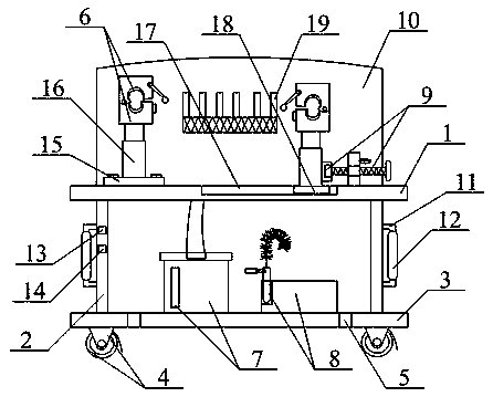
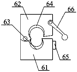
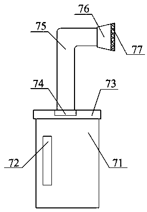
[0037] as attached figure 1 to attach figure 2 As shown, the present invention provides a crankshaft polishing support device with self-cleaning function. Card seat structure 6, filter and adsorption waste cleaning cover structure 7, crankshaft grinding and trimming rod structure 8, cylinder push rod ejector structure that can fix the oil pot 9, rear protective baffle 10, hand push handle 11, anti-slip sleeve 12. Lifting control switch 13, cleaning control switch 14, first fixed seat 15, lifting cylinder 16, moving chute 17, second fixed seat 18 and magnet bar 19, and one end of the support column 2 is bolted to the The four corners of the lower surface of the upper supporting horizontal plate 1, and the other end bolts are connected to the four corners of the upper surface of the lower supporting horizontal plate 3; the moving wheels 4 are respectively bolted to the four corners of the lower surface of the lower supporting horizontal plate 3; The fixed through-holes 5 are ...
PUM
Abstract
The invention provides a crankshaft polishing support device with a self-cleaning function, which comprises an upper support transverse plate, a support column, a lower support transverse plate, a mobile wheel, a fixed through hole, a clampable crankshaft fixed clamping seat structure, a filter adsorption scrap cleaning cover structure, a crankshaft grinding and trimming rod structure, a fixable oil pot air cylinder push rod ejector rod structure, a rear part protective baffle, amanual pushing handle, an anti-skid sleeve, a lifting control switch, a cleaning and dust collecting control switch,a first fixingseat, a lifting air cylinder, a movablesliding groove, a second fixing seat, and a magnet strip. According to the crankshaft polishing support device with the self-cleaning function,thearrangement of a waste collection box, a fixed inserting tube, a manual holding handle, a connecting rod, afile plate, a stainless steel bending strip, and abrush cleaning device are favorable for cleaning the bending portion of the crankshaft after the polishing is completed, the waste collection box is used for collecting, a good working environment is maintained while an unsuitable part is ground and trimmed with the file plate.
Description
technical field [0001] The invention belongs to the technical field of crankshaft machining machinery auxiliary equipment, and in particular relates to a crankshaft polishing support device with a self-cleaning function. Background technique [0002] The crankshaft is an important part of the engine and is responsible for the power output of the engine. An important indicator of crankshaft quality performance is the surface roughness of the crankshaft shaft diameter. If the use requirements are not met, it is very easy to cause destructive accidents such as engine tile burning and tile melting, and in severe cases, the entire engine will be scrapped. In order to improve the surface roughness quality of the crankshaft journal, the journals of the main journal and the connecting rod journal are usually polished. Due to the uneven technical level of crankshaft processing enterprises, there are very few high-level crankshaft processing factories in China. [0003] At present,...
Claims
Application Information
Patent Timeline
Application Date:The date an application was filed.
Publication Date:The date a patent or application was officially published.
First Publication Date:The earliest publication date of a patent with the same application number.
Issue Date:Publication date of the patent grant document.
PCT Entry Date:The Entry date of PCT National Phase.
Estimated Expiry Date:The statutory expiry date of a patent right according to the Patent Law, and it is the longest term of protection that the patent right can achieve without the termination of the patent right due to other reasons(Term extension factor has been taken into account ).
Invalid Date:Actual expiry date is based on effective date or publication date of legal transaction data of invalid patent.