Frock clamp for hub cap end face turning

A technology of face turning and tooling and fixtures, which is applied in the field of tooling and fixtures, can solve the problems of cost, cumbersome replacement, and inability to control the parallelism of two planes, and achieve the effect of stable and reliable fixation and increased clamping speed

Pending Publication Date: 2019-01-18
宁波市慈力金属制品有限公司
View PDF0 Cites 0 Cited by
  • Summary
  • Abstract
  • Description
  • Claims
  • Application Information

AI Technical Summary

Problems solved by technology

[0002] image 3 Shown is a hubcap, its left end face is vertical, now it is necessary to turn the right end face to make it vertical as well. At present, the workshop generally uses a three-jaw chuck to grasp the hub cap, and then turns the right end face, and the three-jaw The chuck can realize the accurate positioning of the hub cover (the three-jaw chuck can be positioned on the outer circumference or the inner circumference, that is, to realize the concentricity or perpendicularity between the turning surface and the central axis, but it cannot control the parallelism between the two planes), but when replacing the hub It is cumbersome to cover, especially when multiple hub covers need to be face turned, half of the time is spent on the positioning of the hub cover on the three-jaw chuck

Method used


Image

  • Frock clamp for hub cap end face turning
  • Frock clamp for hub cap end face turning
  • Frock clamp for hub cap end face turning

Examples


Embodiment Construction

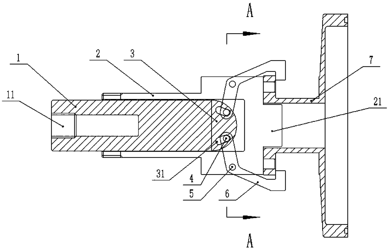
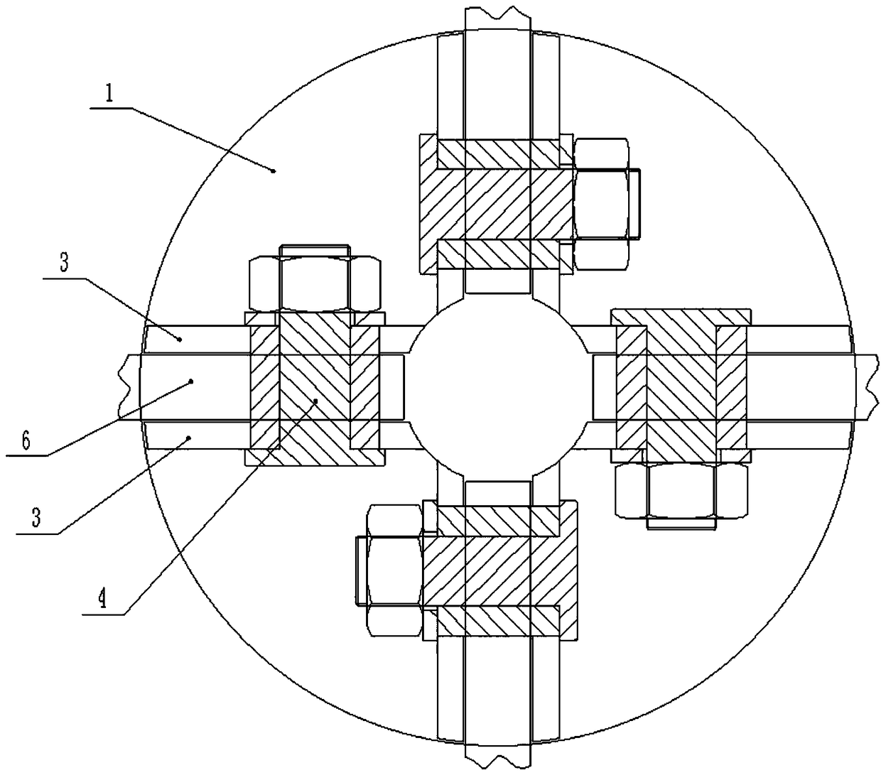
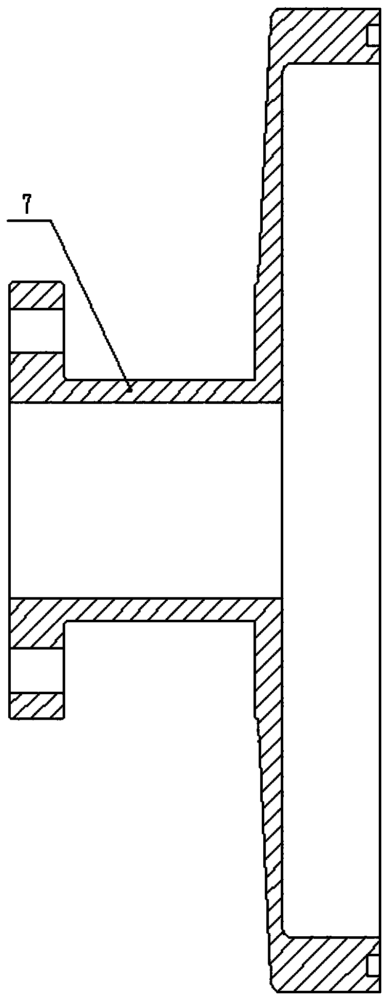
[0016] Such as figure 1 , figure 2 As shown, a tooling fixture for hub cap end face turning according to an embodiment of the present invention includes an outer shaft sleeve 2 fixed on the machine head through threads, placed in the outer shaft sleeve 2 and can be used as a shaft along the outer shaft sleeve 2 The movable shaft 1, the swing arm 6, and the right end surface of the outer shaft sleeve 2 protrude to form a positioning part 21. The size of the positioning part 21 matches the inner diameter of the hub cover 7. The left side of the movable shaft 1 is processed with a threaded hole 11. Hydraulic pressure The ejector rod is screwed into the threaded hole 11 and drives the movable shaft 1 to move. The right end of the movable shaft 1 is fixed with a connecting plate 3 that is a cross. The single connecting plate 3 is semicircular in shape. The connecting plate 3 is processed with an arc-shaped groove 31. The middle part of the swing arm 6 is connected to the outer b...


PUM


Abstract

The invention provides a frock clamp for hub cap end face turning. The frock clamp comprises an outer shaft sleeve, a movable shaft and swing arms, wherein the outer shaft sleeve is fixed on a machinehead through a thread, the movable shaft is arranged in the outer shaft sleeve and can conduct axial motion along the outer shaft sleeve, the right end face of the outer shaft sleeve protrudes to form a positioning part, the size of the positioning part is matched with the inner diameter of a hub cap, a threaded hole is formed in the left side of the movable shaft, a hydraulic jacking rod is screwed into the threaded hole and drives the movable shaft to move, crisscross connecting plates are fixed at the right end of the movable shaft, the single connecting plate is in a semicircular shape, arc-shaped grooves are formed in the connecting plates, the middles of the swing arms are connected to the outer shaft sleeve through hinges, the tails of the swing arms are arranged in the arc-shapedgrooves through pin shafts, the number of the swing arms is four, and the swing arms are distributed uniformly on the outer circumference of the outer shaft sleeve; through the movement of the movableshaft relative to the outer shaft sleeve, opening and closing movements of the swing arms can be achieved, the clamping speed of the hub cap is greatly improved, and through the linkage action of thehydraulic jacking rod and the four swing arms, the fixation of the hub cap is stable and firm.

Description

technical field [0001] The invention relates to a tooling fixture for turning the end face of a hub cover. Background technique [0002] image 3 Shown is a hubcap, its left end face is vertical, now it is necessary to turn the right end face to make it vertical as well. At present, the workshop generally uses a three-jaw chuck to grasp the hub cap, and then turns the right end face, and the three-jaw The chuck can realize the accurate positioning of the hub cover (the three-jaw chuck can be positioned on the outer circumference or the inner circumference, that is, to realize the concentricity or perpendicularity between the turning surface and the central axis, but it cannot control the parallelism between the two planes), but when replacing the hub It is cumbersome to cover, especially when multiple hub covers need to be face turned, half of the time is spent on the positioning of the hub covers on the three-jaw chuck. Contents of the invention [0003] In view of the d...

Claims


Application Information

Patent Timeline
IPC IPC(8): B23Q3/06
CPCB23Q3/062
Inventor 陈利明
Owner 宁波市慈力金属制品有限公司
Why Eureka
Try Eureka