Door lock structure and electrical appliance equipment

A technology of door lock structure and electrical equipment, which is applied in building locks, building structures, buildings, etc., can solve the problems of easy safety accidents and low safety of door lock structures, and achieve the effect of avoiding safety accidents

Active Publication Date: 2019-01-18
WENZHOU TIANJIAN ELECTRIC APPLIANCE
View PDF6 Cites 5 Cited by
  • Summary
  • Abstract
  • Description
  • Claims
  • Application Information

AI Technical Summary

Problems solved by technology

[0006] Therefore, the technical problem to be solved by the present invention is that when the existing door lock structure is in the open state, the cam can drive the toggle piece to turn on the switch when it is pried by other objects, and control the power supply of the electrical equipment to turn on and work, causing the door to open. The safety of the lock structure is low, which is easy to cause safety accidents

Method used


Image

  • Door lock structure and electrical appliance equipment
  • Door lock structure and electrical appliance equipment
  • Door lock structure and electrical appliance equipment

Examples


Embodiment 1

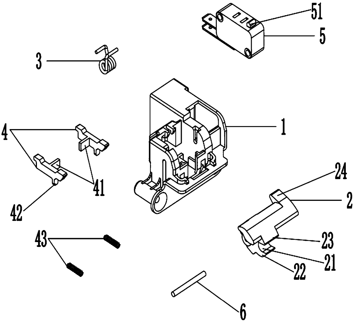
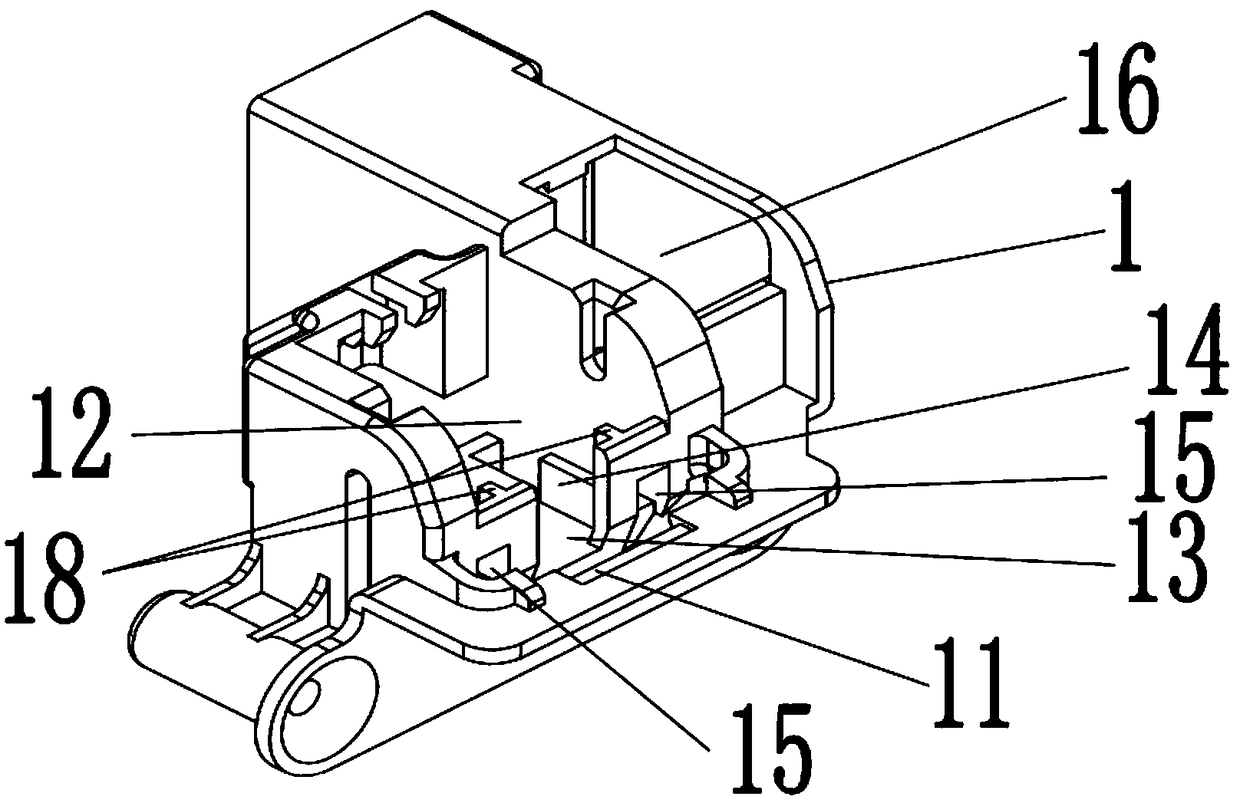
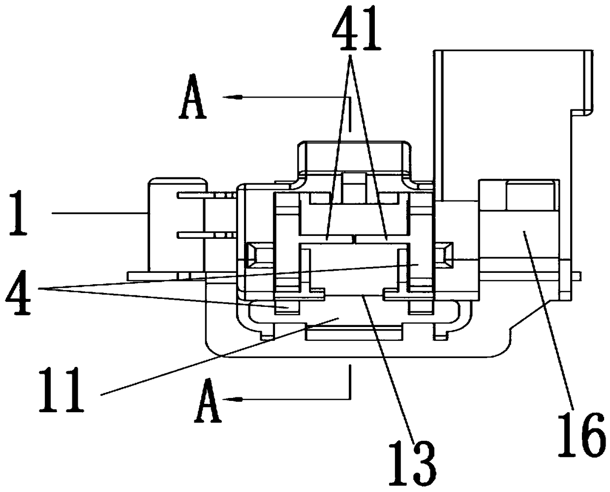
[0077] A kind of door lock structure of this embodiment, as Figure 1 to Figure 20 As shown, it includes a cam 2, a door hook 7, a first elastic member 3, a control switch 5 and at least two limit assemblies 4, wherein the cam 2 is rotatably arranged on the lock seat 1, and the lock seat 1 is provided with a The door hook 7 is inserted into the through hole 11; the lock seat 1 is protruded from the outer wall surface and is provided with a toggle part 24; The moving part 24 presses the control switch 5 provided on the door lock structure to switch between the locked state of the control switch 5 and the unlocked state of pulling out the through hole 11 to release the driving of the cam 2; the first elastic member 3 is located on the Between the lock base 1 and the cam 2, one end is connected to the cam 2, and the other end is fixedly connected to the lock base 1. When the door hook 7 is pulled out from the through hole 11, the cam 2 is biased by the first elastic member 3 and ...

Embodiment 2

[0095] This embodiment provides an electrical device, including the door lock structure in Embodiment 1,

[0096] The main body of the electrical appliance has an inner cavity of the door and a working device arranged in the inner cavity;

[0097] The door panel is rotatably arranged on the door; for the rotation, it can be connected by pivot joints, hinge joints, etc.;

[0098] The lock seat 1 is arranged on one of the door panel and the doorway wall, and the door hook 7 is arranged on the other of the door panel and the doorway wall;

[0099] The control switch 5 is arranged in the cavity 16 on the lock base 1, is electrically connected with the working device, and controls the opening or closing of the working device. The electrical equipment in this embodiment is a dishwasher.

[0100] The working process of the dishwasher is as follows;

[0101] When the dishwasher is closed, if Figure 11 As shown, the door hook 7 enters the through hole 11, presses the front ends of...


PUM


Abstract

The invention discloses a door lock. The door lock includes a cam rotatably arranged on a lock base, a door hook, a first elastic piece and at least two limiting assemblies. A protrusive pulling partis arranged on the cam, the door hook stretches into a through hole and drives the cam to clockwise rotate in order to drive the pulling part to abut against a door lock structure under a locking state or retracts from the through hole in order to remove the limitation of the cam under an unlocking state; the limiting assemblies are retractably arranged at the through hole in the lock base and apply an abutting force for limiting the clockwise rotation of the cam under the unlocking state. According to the door lock structure, when the door hook stretches into the through hole before switchingof the locking state, all the limiting assemblies slide to remove the abutting force performed on the cam under the action of a pulling force of the door lock at the same time. When a screwdriver andother sharp objects are inserted into the through hole, the cam can be unlocked from only one limiting assembly but is still abutted against by the other limiting assemblies and cannot clockwise turnover to switch to the locking state.

Description

technical field [0001] The invention belongs to the technical field of electrical door locks, and in particular relates to a door lock structure and electrical equipment. Background technique [0002] The electrical equipment in the prior art usually includes an electrical main body, a door panel, a door lock, a door hook, a locking device and a control switch. The electrical main body has an installation cavity at the door; , the door hook is fixed on the door, and the control switch controls whether the equipment in the installation cavity is running or not by opening or closing the door panel to make the door lock and the door hook work. [0003] Wherein, the structure of the door lock mainly includes a door lock main body, a cam and a torsion spring, the cam is rotatably installed on the door lock main body, and the torsion spring applies a biasing force to the cam to rotate towards the direction of releasing the combination with the door hook; the locking device Includ...

Claims


Application Information

Patent Timeline
Patent Type & Authority Applications(China)
IPC IPC(8): E05B65/00E05B15/00
CPCE05B15/00E05B15/0013E05B65/00
Inventor 王立孟
Owner WENZHOU TIANJIAN ELECTRIC APPLIANCE
Why Eureka
Try Eureka