Roller assembly and rolling rotor compressor

A technology of compressors and rollers, which is applied in the field of compressors, can solve the problems of poor performance and easy capacity shifting, and achieve the effect of avoiding capacity shifting and improving performance

Active Publication Date: 2019-01-18
GREE ELECTRIC APPLIANCES INC +1
View PDF4 Cites 4 Cited by
  • Summary
  • Abstract
  • Description
  • Claims
  • Application Information

AI Technical Summary

Problems solved by technology

However, in a general rolling rotor compressor, the roller and the sliding vane are two independent parts.

Method used


Image

  • Roller assembly and rolling rotor compressor
  • Roller assembly and rolling rotor compressor
  • Roller assembly and rolling rotor compressor

Examples


Embodiment Construction

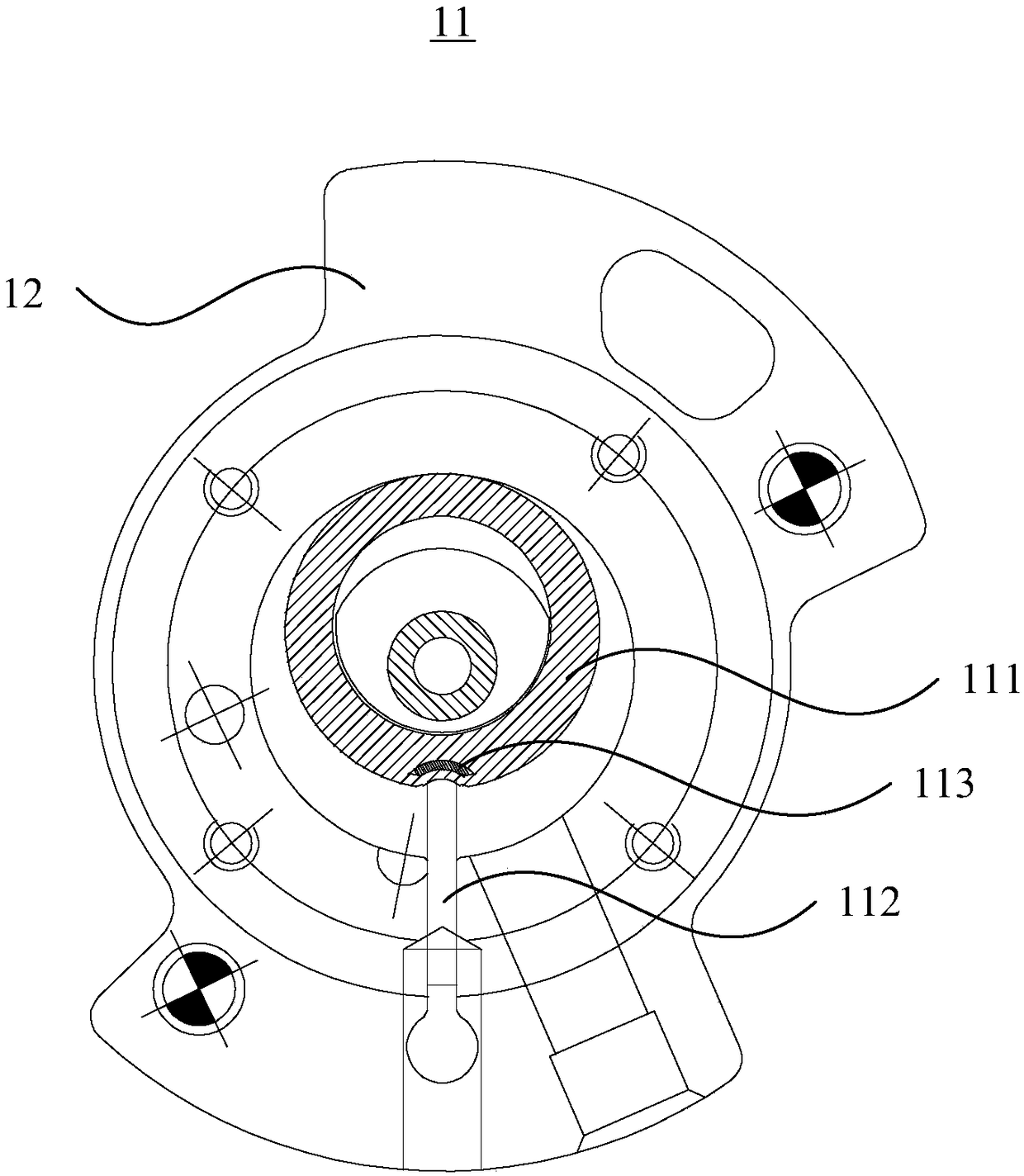
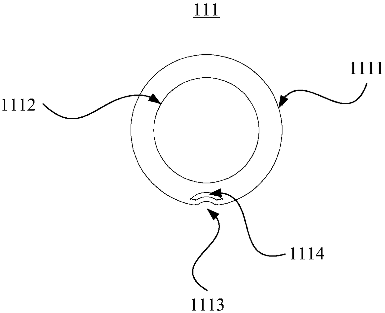
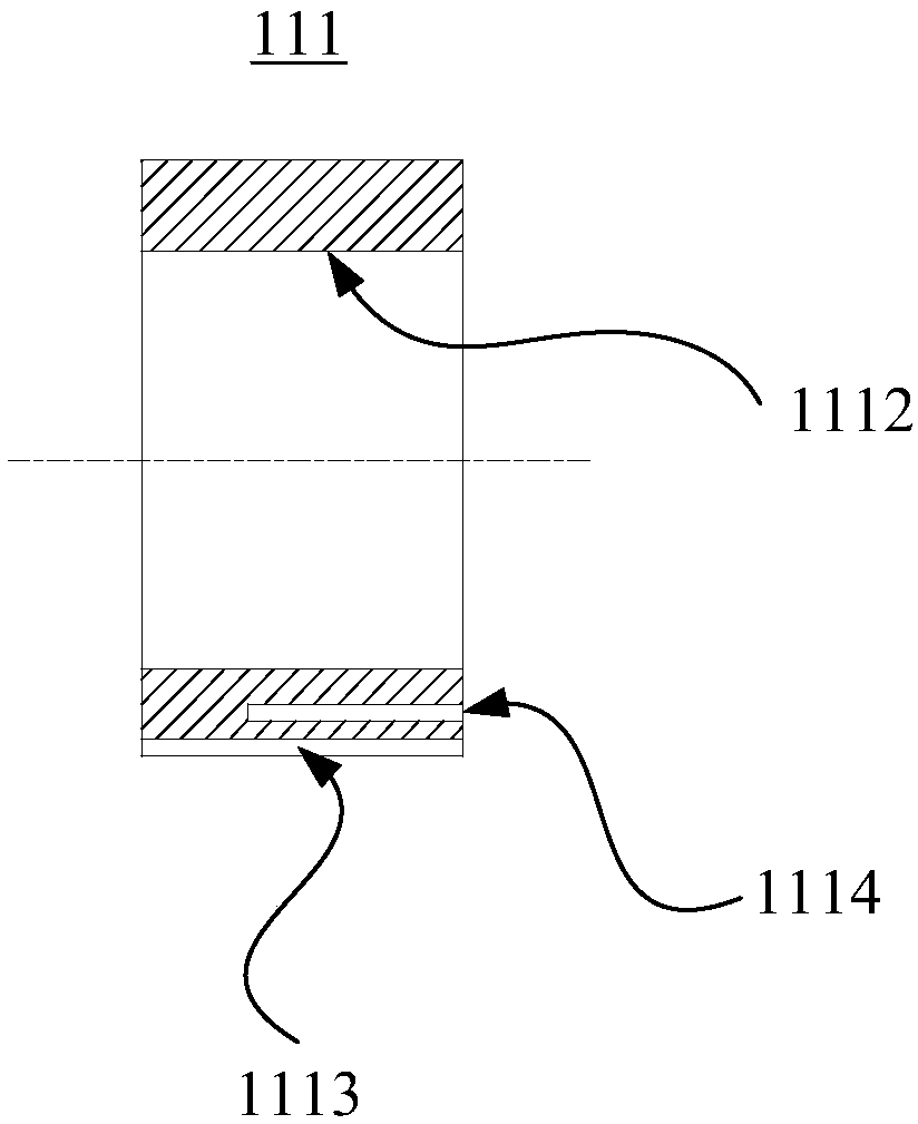
[0023] Such as figure 1 As shown, in one embodiment, a roller assembly 11 is provided, including a roller 111 and a sliding piece 112, the roller 111 can move eccentrically in the cylinder body 12, and the front end of the sliding piece 112 is magnetically attracted Abutting against the outer peripheral surface 1111 of the roller 111 , the rear end of the sliding piece 112 can be inserted into the side wall of the cylinder 12 , forming an air suction chamber and an exhaust chamber in the cylinder 12 .

[0024] The above solution provides a roller assembly 11, the front end of the slide 112 is attracted to the outer peripheral surface 1111 of the roller 111 by magnetic force, so that when the roller 111 moves eccentrically in the cylinder 12, the front end of the slide 112 The front end is always in contact with the outer peripheral surface 1111 of the roller 111, and the sliding plate 112 will not be detached from the roller 111, so that the suction chamber and the exhaust cha...


PUM


Abstract

The invention relates to a roller assembly and a rolling rotor compressor. The roller assembly comprises a roller and a slider, the roller can eccentrically move in a cylinder body, the front end of the slider is adsorbed to the periphery of the roller by magnetic force, the rear end of the slider can be inserted in the sidewall of the cylinder body, and a suction cavity and an exhaust cavity areformed in the cylinder body. Thus, as the roller eccentrically moves in the cylinder body, the front end of the slider always abuts against the periphery of the roller, the situation of the slider separating from the roller cannot occur, so that the situation of capacity fluctuation is effectively prevented, and thereby the overall operating performance is increased.

Description

technical field [0001] The invention relates to the field of compressors, in particular to a roller assembly and a rolling rotor compressor. Background technique [0002] The rolling rotor compressor includes rollers arranged in the cylinder body, and sliding vanes pressed against the outer surface of the rollers under the action of external forces such as spring force. The rollers move eccentrically in the cylinder body, and the sliding vanes are always pressed against the surface of the rollers, thereby realizing the processes of suction, compression and exhaust. However, in a general rolling rotor compressor, the roller and the sliding vane are two independent parts. During the eccentric movement of the roller, the capacity is prone to shifting, and the performance is poor. Contents of the invention [0003] Based on this, it is necessary to provide a roller assembly and a rolling rotor compressor, so as to avoid capacity fluctuation and improve performance. [0004] ...

Claims


Application Information

Patent Timeline
IPC IPC(8): F04C18/356F04C29/00
CPCF04C18/3566F04C29/00
Inventor 卢林高赵旭敏彭慧明蔡庆波
Owner GREE ELECTRIC APPLIANCES INC
Why Eureka
Try Eureka