Micro dynamic pressure generator based on liquid-gas pressure conversion and working method

A dynamic pressure and generator technology, which is applied in fluid pressure actuation devices, fluid pressure actuation system components, fluid pressure measurement, etc., can solve problems affecting service life, small pressure amplitude, piston bending, etc., to improve output Amplitude, increase the pressure amplitude, reduce the effect of lateral displacement

Active Publication Date: 2019-01-18
BEIJING CHANGCHENG INST OF METROLOGY & MEASUREMENT AVIATION IND CORP OF CHINA
View PDF6 Cites 9 Cited by
  • Summary
  • Abstract
  • Description
  • Claims
  • Application Information

AI Technical Summary

Problems solved by technology

However, the vibration displacement of the electromagnetic vibrating table will decrease sharply with the increase of frequency, which will cause the generated pressure amplitude to be small at medium and high frequencies; and the electromagnetic vibrating table will inevitably produce lateral displacement and vibration during use, which will cause the connection The piston is bent or damaged, which greatly affects the service life
Therefore, there are certain defects in existing tiny dynamic pressure generators

Method used


Image

  • Micro dynamic pressure generator based on liquid-gas pressure conversion and working method
  • Micro dynamic pressure generator based on liquid-gas pressure conversion and working method

Examples


Embodiment 1

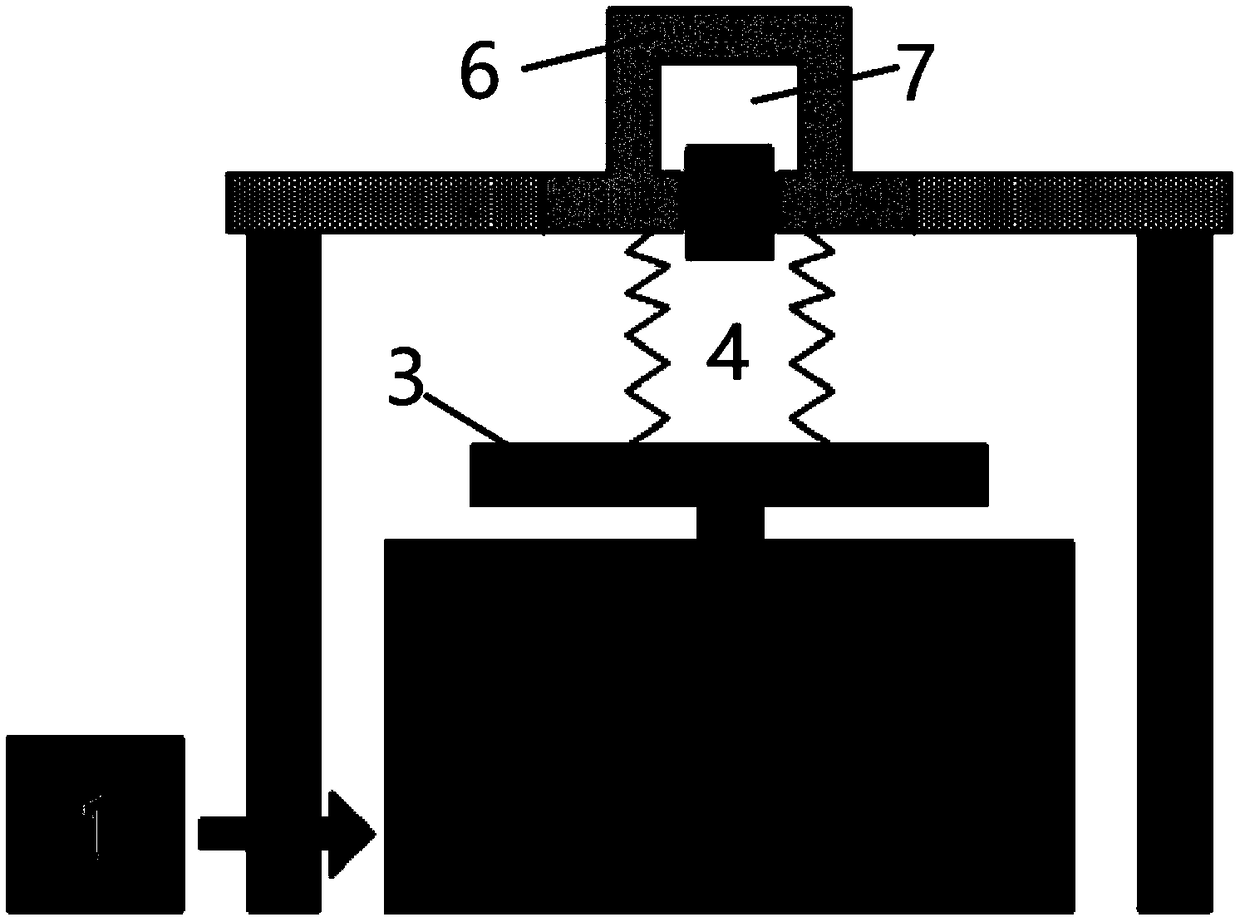
[0029] Such as figure 1 As shown, the tiny dynamic pressure generator based on liquid-pneumatic pressure conversion disclosed in this embodiment consists of a vibrating table controller 1, a vibrating table body 2, a vibrating table surface 3, a variable volume hydraulic cavity 4, a piston 5, a piston cylinder 6, The gas pressure chamber 7 is composed.

[0030] The vibrating table controller 1 is connected to the vibrating table body 2 to control the movement of the vibrating table body 2 .

[0031] The vibrating table body 2 is fixed on the vibration-isolation foundation and vertically fixedly connected with the vibrating table top 3, and the vibrating table body 2 pushes the vibrating table top 3 to move up and down.

[0032] A variable volume hydraulic cavity 4 is fixedly installed on the vibration table 3 .

[0033] In order to change the internal volume of the variable-volume hydraulic cavity 4 under the premise of ensuring the quality of the liquid medium remains uncha...


PUM


Abstract

The invention discloses a micro dynamic pressure generator based on liquid-gas pressure conversion and a working method of the micro dynamic pressure generator, belonging to the technical field of metering and testing. The micro dynamic pressure generator based on the liquid-gas pressure conversion is mainly composed of a vibration table controller, a vibration table body, a vibration table surface, a variable volume hydraulic cavity, a piston, a piston sleeve and a gas pressure chamber; the vibration table controller is connected with the vibration table body; the vibration table body is fixed on the vibration isolation foundation and is vertically fixedly connected with the vibrating table surface, and the vibrating table body pushes the vibrating table surface to move up and down; the variable volume hydraulic cavity is fixedly arranged on the vibration table surface. The invention also discloses a working method of the micro dynamic pressure generator based on liquid-gas pressure conversion. According to the micro dynamic pressure generator, the pressure amplitude generated by the micro dynamic pressure generator in medium and high frequency can be improved, and the influence of lateral displacement and vibration of the vibration table surface on the life of the piston can be reduced or eliminated. The micro dynamic pressure range means that the pulsating pressure of 0.1kPato 10kPa can be generated in an environment of absolute pressure of 20kPa to 300kPa.

Description

technical field [0001] The invention belongs to the technical field of metering and testing, and relates to a tiny dynamic pressure generator based on liquid-gas pressure conversion and a working method. Background technique [0002] Micro dynamic pressure generator is an indispensable part of the standard device for dynamic calibration of micro gauge pressure or micro differential pressure sensor. The existing micro dynamic pressure generator uses a vibrating table to excite the piston in the gas pressure chamber, and the piston compresses the gas medium to make the volume of the gas medium produce sinusoidal or pulse changes, thereby generating micro sinusoidal pressure or pulse pressure within a certain average pressure range. However, the vibration displacement of the electromagnetic vibrating table will decrease sharply with the increase of frequency, which will cause the generated pressure amplitude to be small at medium and high frequencies; and the electromagnetic vi...

Claims


Application Information

Patent Timeline
Patent Type & Authority Applications(China)
IPC IPC(8): F15B21/12G01L27/00G01L25/00
CPCF15B21/12G01L25/00G01L27/005
Inventor 杨军李博黄日恒
Owner BEIJING CHANGCHENG INST OF METROLOGY & MEASUREMENT AVIATION IND CORP OF CHINA
Why Eureka
Try Eureka