
Powder bin material level meter for mechanical production

A material level meter and powder silo technology, applied in the field of material level meter, can solve the problems that the material level meter is inconveniently fixed inside the storage bin, inconveniently fixed inside the silo, and the material level measurement is not accurate enough, so as to improve the cleanliness , improve the stability of use, and solve the effect of inconvenient cleaning

Inactive Publication Date: 2019-01-18
合肥昌燎科技有限公司
View PDF0 Cites 0 Cited by
  • Summary
  • Abstract
  • Description
  • Claims
  • Application Information

AI Technical Summary

Problems solved by technology

[0003] The existing powder silo level gauges for mechanical production are inconveniently fixed inside the silo. When the level gauge measures the material level of the silo, the level gauge often needs to be placed inside the silo, but most of the level gauges are inconvenient to be fixed in the storage silo. Inside the silo, so that the material level measurement is not accurate enough. The existing powder silo material level gauge for mechanical production is inconvenient to clean. The material level gauge is placed inside the storage silo for material level measurement. More materials will adhere, resulting in inaccurate material level measurement. Now there is an urgent need for a powder bin level meter for mechanical production to solve the above problems

Method used


Image

  • Powder bin material level meter for mechanical production
  • Powder bin material level meter for mechanical production
  • Powder bin material level meter for mechanical production

Examples


Embodiment Construction

[0021] In order to make the technical means, creative features, goals and effects achieved by the present invention easy to understand, the present invention will be further described below in conjunction with specific embodiments.

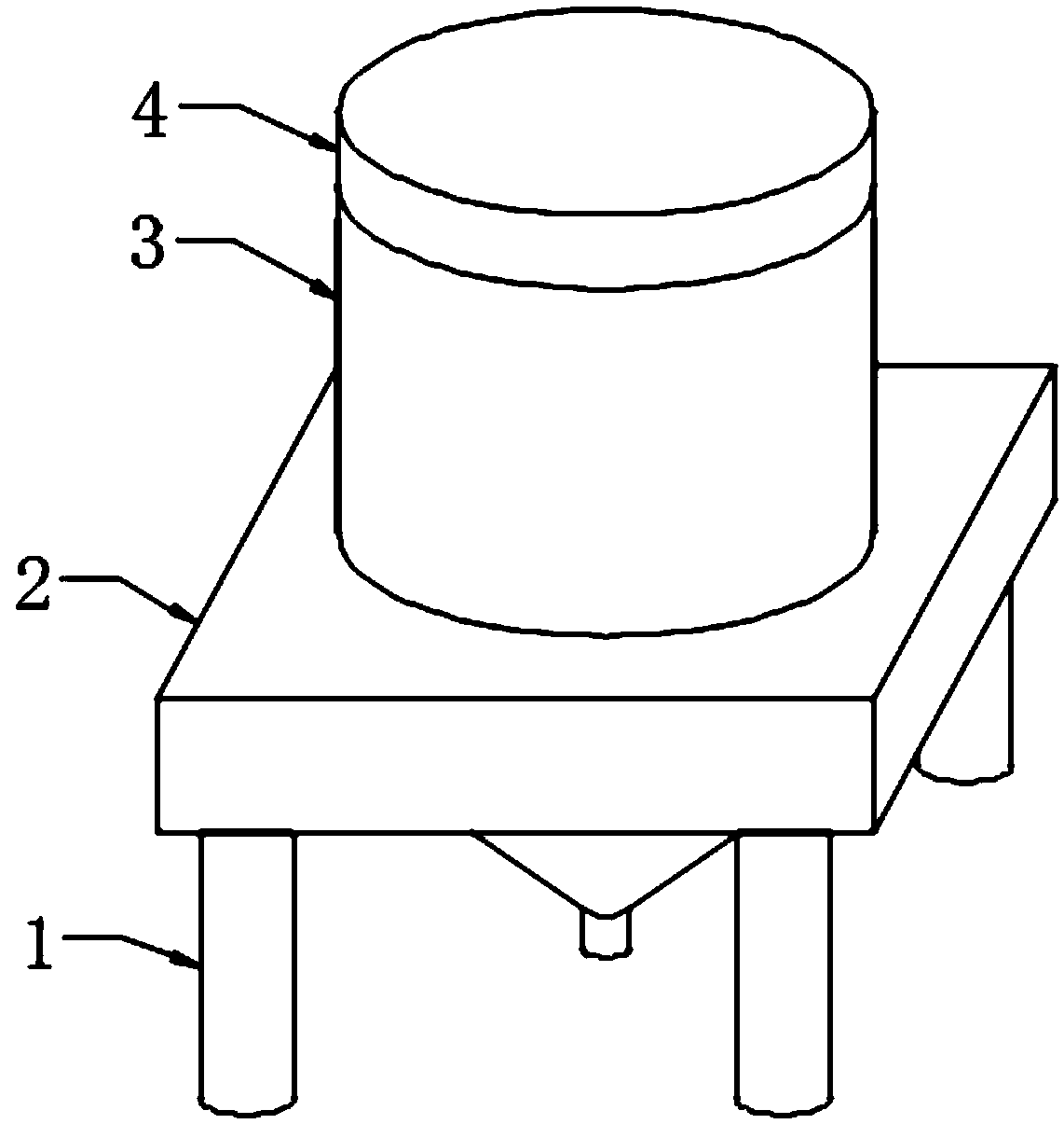
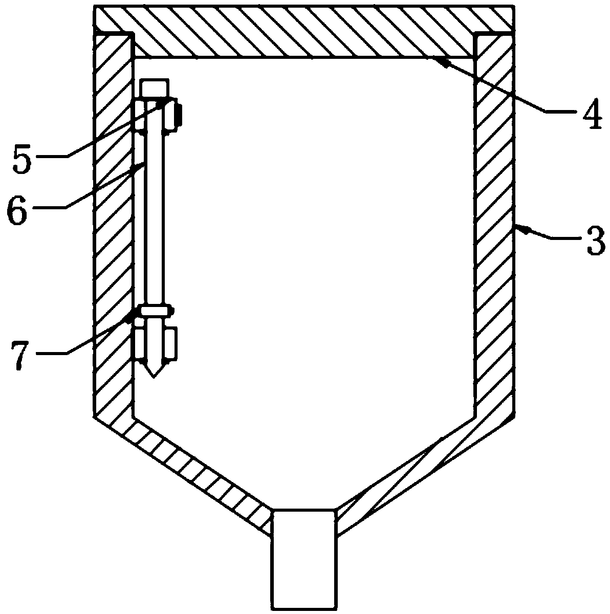
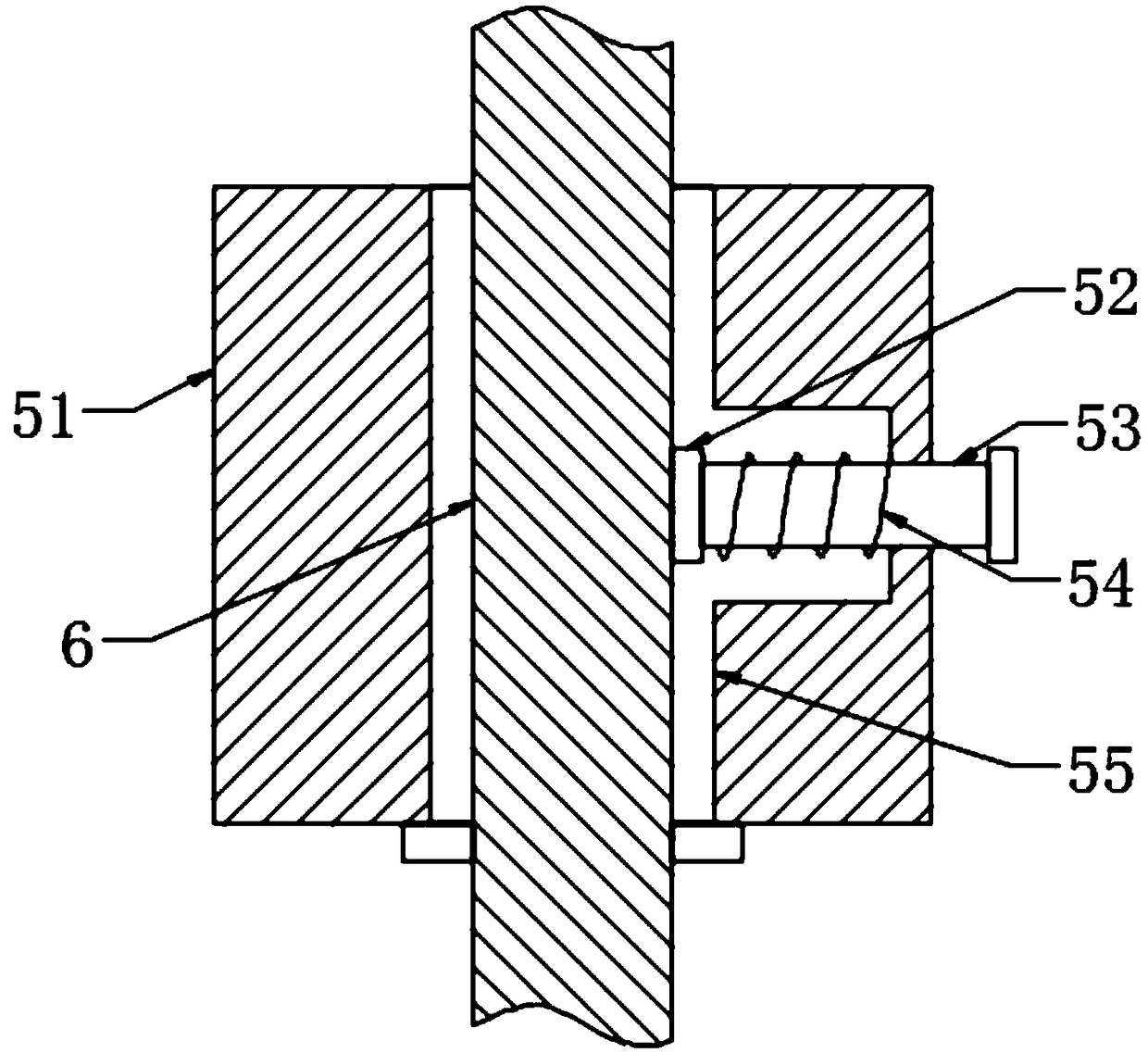
[0022] see Figure 1-Figure 5 , the present invention provides a technical solution: a powder bin material level meter for mechanical production, including a support column 1, a placement table 2, a powder bin 3, a bin cover 4, a fixing mechanism 5, a material level meter main body 6 and a cleaning mechanism 7 , the support column 1 is installed on the lower end surface of the placing table 2, the powder bin 3 is installed on the middle position inside the placing table 2, the bin cover 4 is installed on the upper end face of the powder bin 3, the main body of the level gauge 6 is installed on the left side of the inside of the powder bin 3, fixed The mechanism 5 is arranged on the left side of the inner wall of the powder bin 3, and the cleaning ...


PUM


Abstract

The invention provides a powder bin material level meter for mechanical production, which comprises an upper support, an arc-shaped plate, a drawbar, a spring, a lower support, a handle, a mounting ring, a cleaning sleeve and a cleaning head. The upper support is installed on the left side of the inner wall of a powder bin; the lower support is installed directly below the upper support; the arc-shaped plate is installed on the right side of an annular side surface of the main body of the material level meter; the drawbar is installed on the right end surface of the arc-shaped plate; and the spring is sleeved on the annular side surface of the drawbar. The design solves the problem that it is inconvenient for fixing the former powder bin material level meter for mechanical production inside the material bin. The mounting ring is sleeved on the annular side surface of the main body of the material level meter; the handle is welded on the left and right sides of the mounting ring; the cleaning sleeve is installed on the inner annular side surface of the mounting ring; and the cleaning head is installed on the inner annular side surface of the cleaning sleeve. The design solves the problem that it is inconvenient for cleaning the former powder bin material level meter for mechanical production. The powder bin material level meter for mechanical production in the invention is reasonable in structure, convenient for fixing and mounting, convenient and fast for cleaning and accurate in measurement.

Description

technical field [0001] The invention is a powder bin material level meter for mechanical production, which belongs to the technical field of material level meters. Background technique [0002] The material level meter refers to the instrument that detects the change of the height of the solid material in the container in real time. When used, it can measure the surface position of the solid block or powder in the storage bin to know the quantity of the material stored in the storage bin. The material level meter is also called the material level transmitter, the material level controller, the material level meter, the material level meter and so on. [0003] The existing powder silo level gauges for mechanical production are inconveniently fixed inside the silo. When the level gauge measures the material level of the silo, the level gauge often needs to be placed inside the silo, but most of the level gauges are inconvenient to be fixed in the storage silo. Inside the silo...

Claims


Application Information

Patent Timeline
IPC IPC(8): G01F23/00
CPCG01F23/00
Inventor 卫洁
Owner 合肥昌燎科技有限公司
Learn More