Electromechanical protection device

An electromechanical protection and mobile device technology, applied in the direction of anti-seismic equipment, can solve the problems of poor practicability of the distribution box, unable to absorb shock, easy to shake or dump, etc., so as to avoid waste of time and increase of cost, and solve inconvenience Dismantling and improving the effect of protection

Inactive Publication Date: 2019-01-18
YANGTZE NORMAL UNIVERSITY
View PDF9 Cites 1 Cited by
  • Summary
  • Abstract
  • Description
  • Claims
  • Application Information

AI Technical Summary

Problems solved by technology

The patent of CN207354765U discloses an electromechanical protection device, through the cooperation between the screw, the protective cover, the embedded fixing plate and the embedded connecting plate, the stability of the protection device is improved, and the shaking is prevented when it is subjected to an external force. However, The existing protection device has poor protection and cannot absorb external force, which may easily cause damage to the protection device
[0004] The patent of CN107769030A discloses an outdoor distribution box. Through the cooperation between the cover plate, the frame shaft and the lock cylinder, the safety of the distribution box in use is realized, and the facilities in the distribution box can be protected. However, the distribution box has poor stability, and it is easy to shake or fall when it is subjected to external forces in the field, which will cause the facilities in the distribution box to fail to operate normally, and even cause serious consequences
[0005] The patent of CN107895895A discloses a distribution box, which realizes the function of adjusting the width of the box body through the cooperation between the shaft rod, the spring and the support arm. However, the practicability of the distribution box is poor. After different boxes, it will not be able to be stably fixed, and cannot be applied to distribution boxes of different sizes

Method used


Image

  • Electromechanical protection device
  • Electromechanical protection device
  • Electromechanical protection device

Examples


Embodiment Construction

[0031] The following will clearly and completely describe the technical solutions in the embodiments of the present invention with reference to the accompanying drawings in the embodiments of the present invention. Obviously, the described embodiments are only some, not all, embodiments of the present invention.

[0032] The same numbers in the drawings represent the same or similar components. On the other hand, well-known components and steps are not described in the embodiments to avoid unnecessary limitations on the present invention.

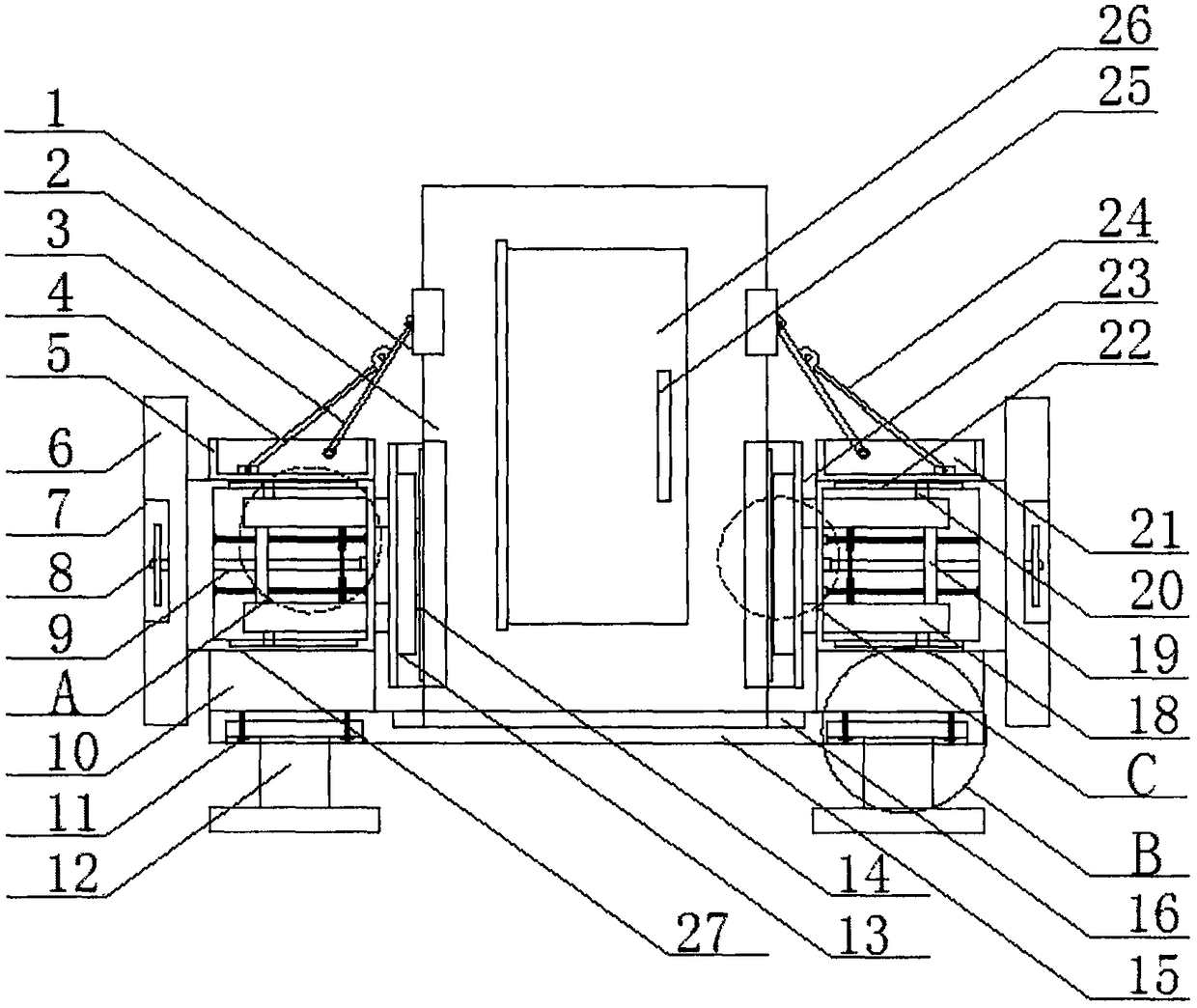
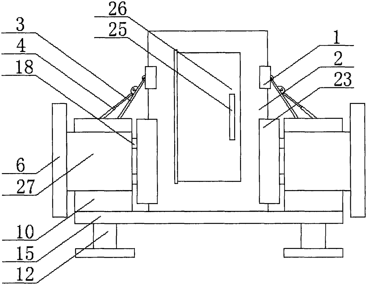
[0033] Such as figure 1As shown, it is a schematic diagram of the internal structure of a kind of electromechanical protection device proposed by the embodiment of the present invention, wherein the I-beam 12 is fixed on the appropriate position on the ground, and then four limit grooves 36 are set at the lower end of the bearing plate 15, and the work The beam 12 and the upper end and the limit groove 36 are correspondingly socketed, and t...


PUM


Abstract

An electromechanical protection device includes a carrier plate, the upper end of the bearing plate is provided with a placing groove, A cabinet body is arranged at the bottom of the placing groove, both sides of the upper end of the bearing plate are fixed with fixing blocks, The upper end of the fixing block is fixed with a connecting block, a cavity is arranged in the connecting block, a movingdevice is arranged in the cavity, a baffle plate is fixed on one side of the connecting block, and one end of the moving device penetrates the side wall of the cavity and extends to one side of the connecting block. The invention solves the problem that when the distribution cabinet is subjected to external force, The utility model has the advantages of being unable to stably fix and damp the vibration, improving the stability and protection, and solving the problem that the distribution cabinet cannot be adjusted according to the size of the distribution cabinet. The utility model has strongpracticability, avoids the damage of the equipment in the distribution cabinet caused by the external force acting on the distribution cabinet, saves the cost, is simple to operate and is convenientto use.

Description

technical field [0001] The invention relates to the field of electromechanical technology, in particular to an electromechanical protection device. Background technique [0002] Electromechanical is the combination of mechanical technology and electronic technology. At present, distribution boxes are often used in the field of electromechanical. , protective electrical appliances and auxiliary equipment are assembled in closed or semiclosed metal cabinets or on screen widths to form low-voltage distribution boxes. During normal operation, the circuit can be connected or disconnected by means of a manual or automatic switch. The distribution box has the advantages of small size, easy installation, special technical performance, fixed position, unique configuration function, and is not limited by the site. It is widely used, stable and reliable in operation, and space-saving. It has the characteristics of high utilization rate, less land occupation and environmental protectio...

Claims


Application Information

Patent Timeline
IPC IPC(8): H02B1/54
Inventor 万浩川何仁琪黄江波
Owner YANGTZE NORMAL UNIVERSITY
Why Eureka
Try Eureka