Supercharge Your Innovation With Domain-Expert AI Agents!

A manufacture auxiliary processing device for an electric motor

An auxiliary processing and motor technology, applied in the manufacture of the stator/rotor body, etc., can solve the problems of stator core cleaning, poor cleaning effect, labor occupation, etc., and achieve the effect of improving efficiency, comprehensive cleaning, and large blowing force

Active Publication Date: 2019-01-18
滁州微秒精密机械有限公司
View PDF7 Cites 3 Cited by
  • Summary
  • Abstract
  • Description
  • Claims
  • Application Information

AI Technical Summary

Problems solved by technology

[0004] The motor is generally composed of end cover, stator, outlet box, position speed sensor and fan, etc. The stator mainly includes the machine base, stator core and winding, and the rotor mainly includes the shaft, rotor core and magnetic steel; the manufacturing process of the motor includes The machining process of parts, the manufacturing process of the iron core, the manufacturing process of the winding, the manufacturing process of the rotor and the assembly process of the motor; the most important step in the manufacturing process of the iron core is the cleaning of the iron core. The quality and stability of the motor are directly linked. At present, manual wiping and partial automatic cleaning are mostly used for cleaning the motor stator core. The cleaning effect is poor, and it also takes up a lot of labor and is inefficient; The following problems generally exist in cleaning machines: (1) The stator core cannot be cleaned comprehensively, only part of the stator core can be cleaned, and the cleaning effect is poor; (2) The replacement is poor and the function is few. The iron core slots have different shapes and many models and sizes, and now many machines can only clean a specific stator core

Method used


Image

  • A manufacture auxiliary processing device for an electric motor
  • A manufacture auxiliary processing device for an electric motor
  • A manufacture auxiliary processing device for an electric motor

Examples


Embodiment Construction

[0032] In order to make the technical means, creative features, goals and effects achieved by the present invention easy to understand, the present invention will be further described below in conjunction with specific illustrations.

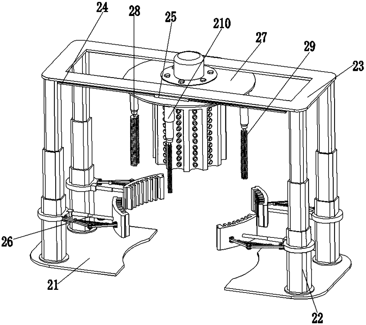
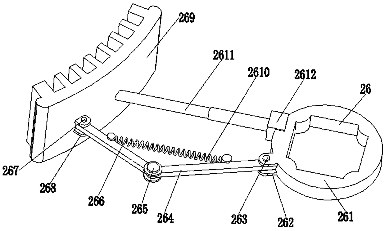
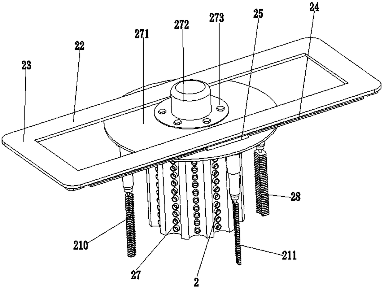
[0033] Such as Figure 1 to Figure 8As shown, an auxiliary processing device for motor manufacturing, including a base 21, a lifting hydraulic cylinder 22, a top plate 23, a moving slide rail 24, a moving slider 25, an external cleaning mechanism 26, a blowing mechanism 27, and a first slot cleaning mechanism. Mechanism 28, the second slot cleaning mechanism 29, the third slot cleaning mechanism 210 and the fourth slot cleaning mechanism 211; Concave arc-shaped mouth, the number of lifting hydraulic cylinders 22 is four, and the lifting hydraulic cylinders 22 are symmetrically installed on the two bases 21 respectively in pairs. The top plate 23 is fixed on the top of the lifting hydraulic cylinders 22. The slide rails 24 are respectively symme...


PUM


Abstract

A manufacture auxiliary processing device for electric motor includes the base, a lifting hydraulic cylinder, a top plate, moving rails, a move slider, an exterior cleaning mechanism, a punch-blow mechanism, a first slot cleaning mechanism, a second slot cleaning mechanism, a third slot cleaning mechanism and a fourth slot cleaning mechanism; every two lifting hydraulic cylinders are symmetricallymounted on two base, a top plate is fixed on that top end of the lifting hydraulic cylinder, a moving slide rail is symmetrically positioned on the front and rear sides of the square groove, a movingslide block is installed on the moving slide rail, an external cleaning mechanism is fixed at the bottom position of the lifting hydraulic cylinder, and a punching and blowing mechanism is installedon the moving slide block. The invention can clean the stator iron core of the electric motor of the distribution station, the cleaning is comprehensive and the cleanliness is high, and the overall mechanical automation degree is high, a large amount of labor is saved, and the production efficiency of the electric motor of the distribution station is improved.

Description

[0001] The present invention is a divisional application of a Chinese patent application filed on December 23, 2016 with the application number 2016112075544 and the title of the invention is a Chinese patent application for an intelligent cleaning robot for the stator core of a distribution station motor. technical field [0002] The invention relates to the field of electric motor auxiliary machinery, in particular to an auxiliary processing device for electric motor manufacturing. Background technique [0003] The distribution station is a place to change the voltage. In order to transmit the electric energy from the power plant to a distant place, the voltage must be raised and turned into high-voltage electricity, and the voltage must be lowered as needed near the user. The work of the distribution station is completed by the distribution station; the main equipment of the distribution station is a switch and a transformer, but there are also some electric auxiliary equi...

Claims


Application Information

Patent Timeline
Patent Type & Authority Applications(China)
IPC IPC(8): H02K15/02
CPCH02K15/02
Inventor 潘学勇
Owner 滁州微秒精密机械有限公司
Features
  • R&D
  • Intellectual Property
  • Life Sciences
  • Materials
  • Tech Scout
  • Unparalleled Data Quality
  • Higher Quality Content
  • 60% Fewer Hallucinations
Learn More