

Substrate equipment and producing method thereof
A manufacturing method and equipment technology, applied in shearing machine equipment, metal processing equipment, manufacturing tools, etc., can solve the problems of large cutting size error, single function, and low work efficiency
Inactive Publication Date: 2019-01-22
众顶(广州)科技有限公司
View PDF0 Cites 0 Cited by
- Summary
- Abstract
- Description
- Claims
- Application Information
AI Technical Summary
Problems solved by technology
When producing adhesive-free copper-clad laminates, it is necessary to cut and process the adhesive-free copper-clad laminates. The current cutting equipment usually only has a one-way cutting function, and its function is single. It is necessary to manually adjust the direction of the adhesive-free copper-clad laminates during cutting. The operation is cumbersome and the work efficiency is low. Moreover, the cutting process of the glueless copper clad laminate requires manual control operation, the cutting size error is large, and the replacement steps of the rotating cutter body are cumbersome. Therefore, it needs to be improved.
Method used
View moreImage
Smart ImageViewing Examples

Examples
Embodiment Construction
Login to View More PUM
 Abstract
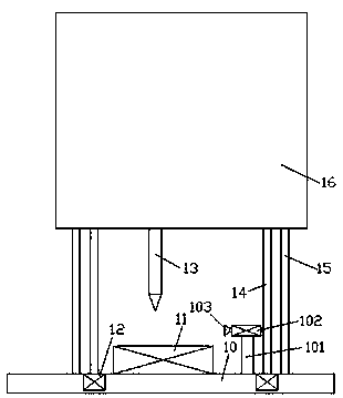
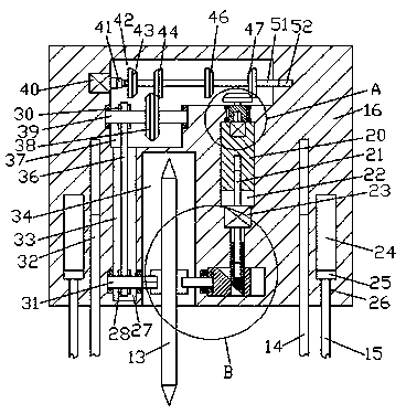
The invention discloses substrate equipment and a producing method thereof. Ultra-thin non-adhesive-coating copper plate equipment is used, the ultra-thin non-adhesive-coating copper plate equipment comprises a processing seat and a lifting and lower member arranged on the lower side of the processing seat, an assembling groove is formed in the end face of the bottom of the processing seat, a rotary cutter body is arranged in the assembly groove, protruded handles are symmetrically and fixedly arranged on the two side end faces of the rotary cutter body taking the center of end faces as the axial center, a first spline cavity is formed in the left side end face of protruded handle on the left side, an inserting cavity is formed in the right side end face of the protruded handle on the right side, a first conveying cavity extending up and down is formed in the left side of the assembly groove, a first rotary rod is rotatably and cooperatively installed on the part on the lower side of the first conveying cavity, a first conveying wheel is fixedly arranged on the outer surface of the first rotary rod, the rear end of the right side of the first rotary rod extends to the interior of the assembly groove to be fixedly provided with a first spline shaft, the first spline shaft is in spline cooperative connection with the first spline cavity, and a second conveying cavity is communicated with the top wall of the first delivery cavity.
Description
technical field The invention relates to the technical field of glue-free copper-clad laminate processing, in particular to a base material device and a manufacturing method thereof. Background technique When producing adhesive-free copper-clad laminates, it is necessary to cut and process the adhesive-free copper-clad laminates. The current cutting equipment usually only has a one-way cutting function, and its function is single. It is necessary to manually adjust the direction of the adhesive-free copper-clad laminates during cutting. The operation is cumbersome and the work efficiency is low. Moreover, the cutting process of the glueless copper-clad laminate requires manual control operation, the cutting size error is large, and the replacement steps of the rotating cutter body are cumbersome. Therefore, it needs to be improved. Contents of the invention The object of the present invention is to provide a substrate device and a manufacturing method thereof, which are u...
Claims
Login to View More Application Information
Patent Timeline
 IPC IPC(8): B23D19/00B23D35/00
CPCB23D19/00B23D35/007
Inventor曾志华
Owner众顶(广州)科技有限公司