Motor rotor molding mold and motor rotor processing method

A technology for motor rotors and forming molds, which is applied in the manufacture of stator/rotor bodies, etc., can solve the problems of low efficiency of motor rotors, and achieve the effect of reducing costs and reducing production and processing steps

Pending Publication Date: 2019-01-22
CHANGZHOU INST OF LIGHT IND TECH
View PDF5 Cites 1 Cited by
  • Summary
  • Abstract
  • Description
  • Claims
  • Application Information

AI Technical Summary

Problems solved by technology

[0004] The technical problem to be solved by the present invention is: to overcome the deficiencies of the prior art, to provide a forming mold for motor rotors and a processing method for motor rotors, and to solve the problem of low efficiency in processing motor rotors in the past

Method used


Image

  • Motor rotor molding mold and motor rotor processing method
  • Motor rotor molding mold and motor rotor processing method
  • Motor rotor molding mold and motor rotor processing method

Examples


Embodiment Construction

[0024] The present invention will be further described in conjunction with specific embodiment now. These drawings are simplified schematic diagrams only to illustrate the basic structure of the present invention in a schematic way, so they only show the components relevant to the present invention.

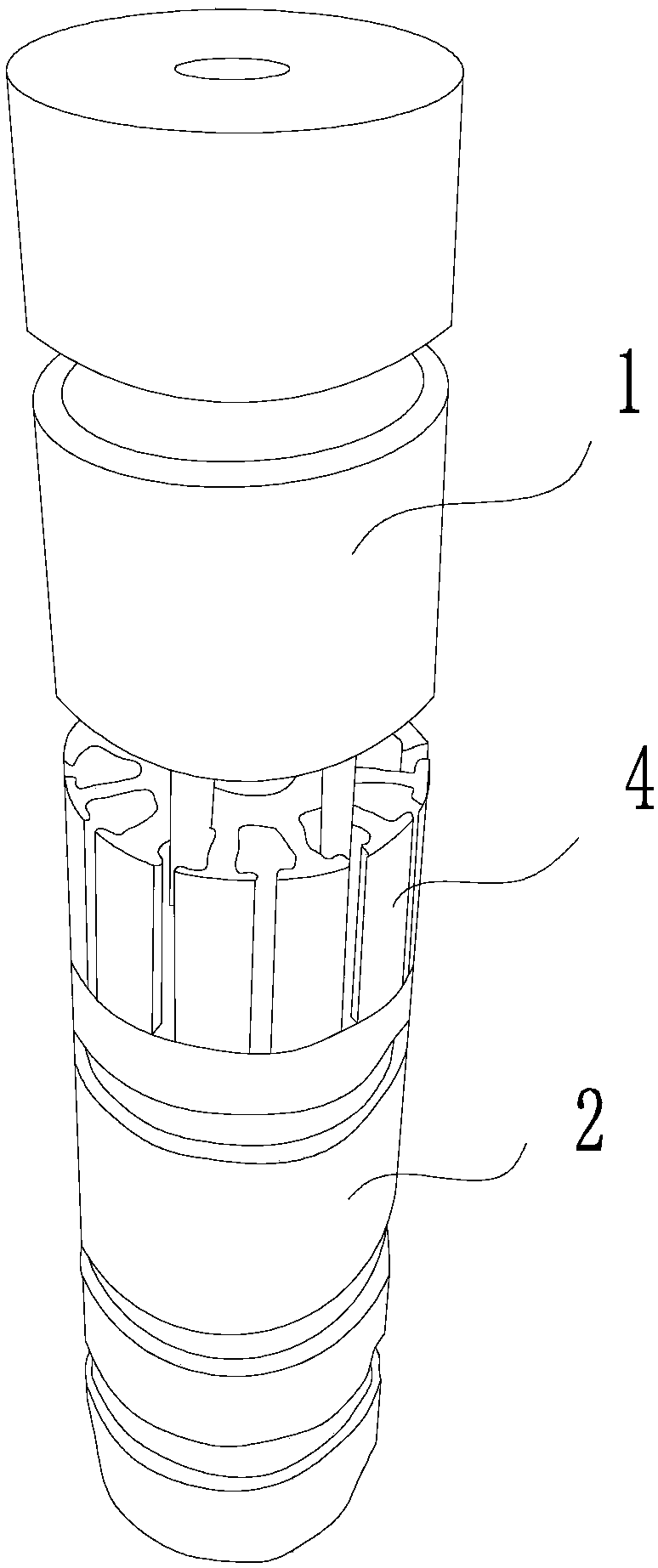
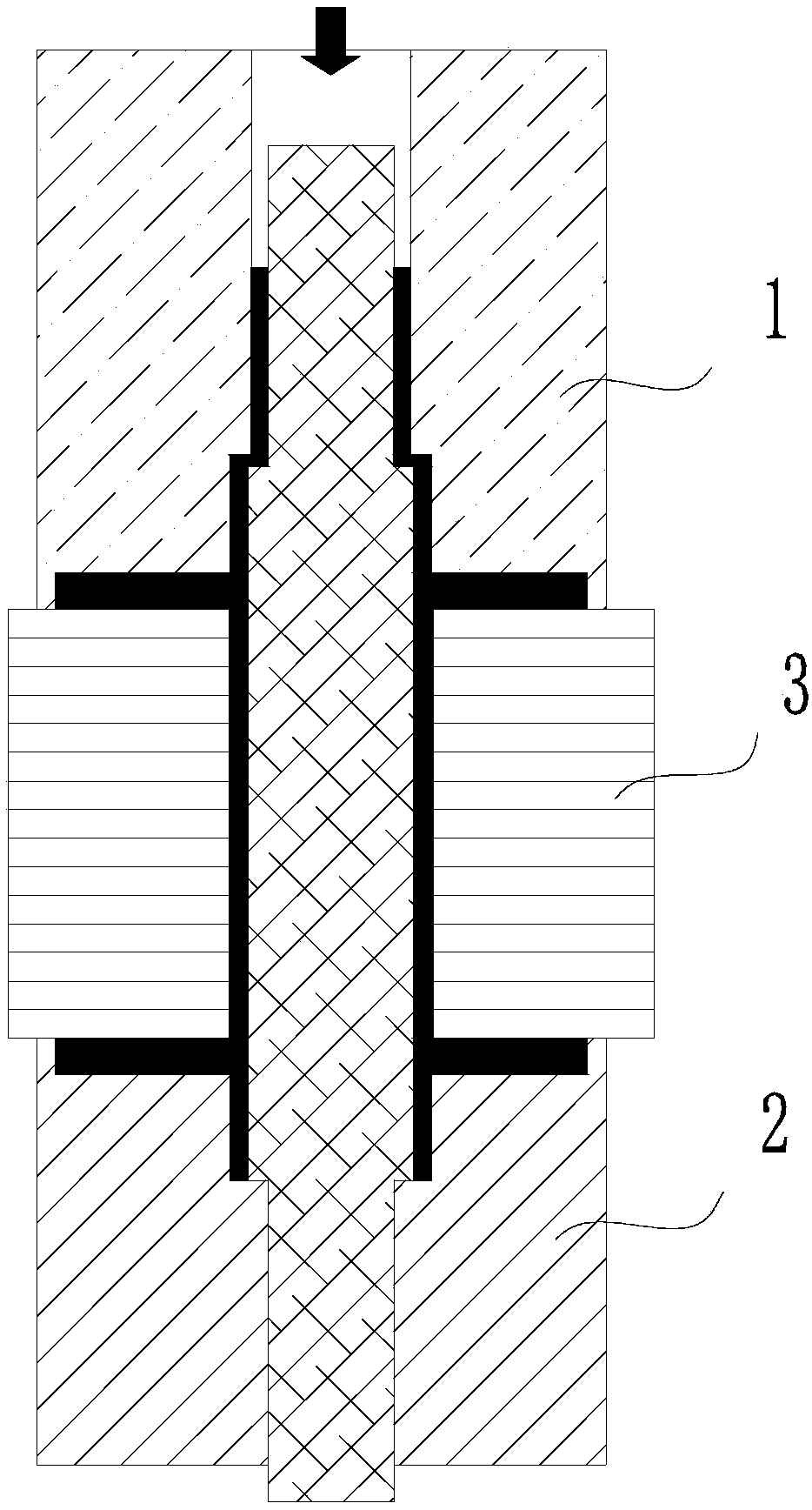
[0025] Such as Figure 1 to Figure 6 As shown, a forming mold for a motor rotor includes a lower mold 2 and an upper mold 1. The center of the upper mold 1 is provided with an upper casting hole, and the upper casting hole runs through the upper mold 1 up and down. The lower end of the upper mold 1 is provided with an upper end plate groove, and the upper casting The lower end of the hole communicates with the upper end plate groove.

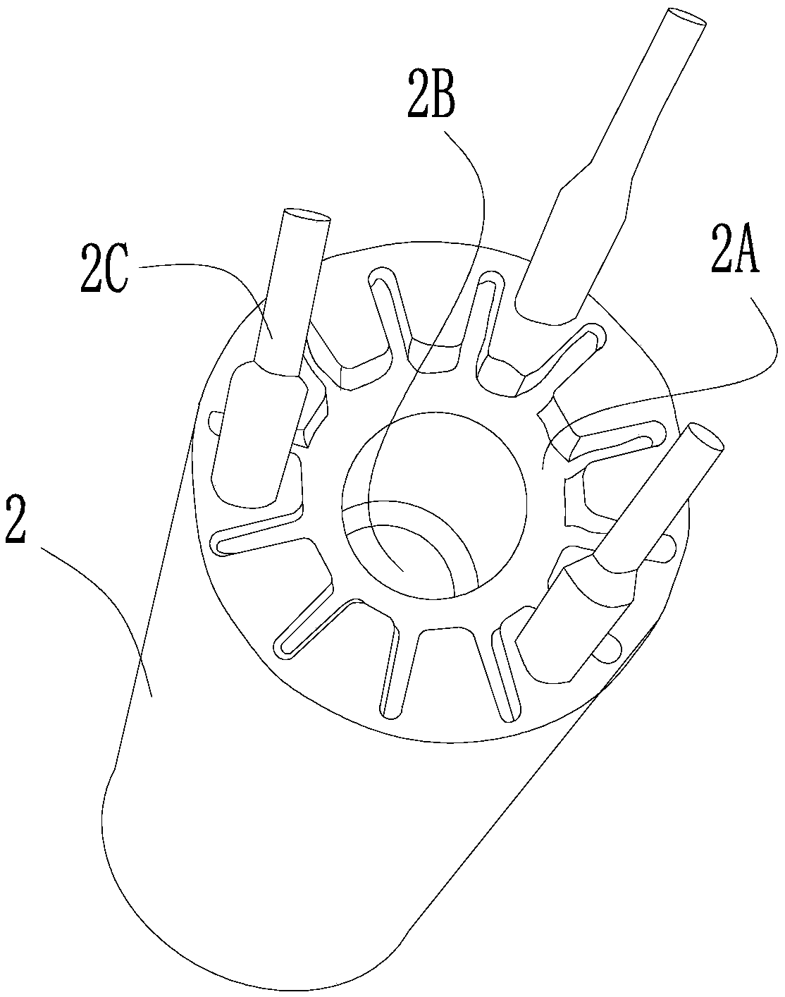
[0026] The upper end of the lower die 2 is provided with a lower end plate groove 2A, and the lower end plate groove 2A is provided with a fixed shaft hole 2B for fixing the motor shaft 3 , and the fixed shaft hole 2B runs through the lower die 2 ...


PUM


Abstract

The invention relates to a motor rotor molding mold, which comprises a lower mold and an upper mold, wherein the center of the upper mold is provided with an upper casting hole, the lower end surfaceof the upper mold is provided with an upper end plate groove, the upper end of the lower mold is provided with a lower end plate groove, and a fixed shaft hole is arranged below the lower end plate groove. The motor rotor processing method uses the molding mold, and comprises: S1, inserting the lower end of a motor rotating shaft into the fixed shaft hole; S2, placing a rotor punching sheet on theupper end surface of the lower mold, wherein a lower end plate casting cavity is formed between the lower end surface of the rotor punching sheet and the lower end plate groove, and an insulating layer casting cavity is formed between the motor rotating shaft and the inner wall of the shaft hole; S3, placing the upper mold on the upper end of the rotor punching sheet, wherein an upper end plate casting cavity is formed between the upper end of the rotor punching sheet and the upper end plate groove; and S4, injecting a casting liquid from the upper casting hole, and taking out a motor statorafter carrying out cooling curing. According to the present invention, the production processing steps are reduced, the processing efficiency is improved while the quality of the motor rotor is ensured, and the cost can be reduced.

Description

technical field [0001] The invention relates to a forming mold for a motor rotor and a processing method for the motor rotor. Background technique [0002] The motor rotor includes two parts: the motor shaft and the rotor punch. In the past, the process of processing the motor rotor was as follows: first make an insulating layer on the outside of the motor shaft, then set the rotor punch outside the insulation layer, and then set the two ends of the rotor punch. End plate, the main purpose of the two end plates is to limit the movement of the rotor punch on the motor shaft. [0003] In the past, this method of processing the motor rotor needs to be processed in two steps, and the processing time is long and the production efficiency is low. Contents of the invention [0004] The technical problem to be solved by the present invention is: to overcome the deficiencies of the prior art, provide a forming mold for the motor rotor and a processing method for the motor rotor, a...

Claims


Application Information

Patent Timeline
Patent Type & Authority Applications(China)
IPC IPC(8): B29C39/10B29C39/26H02K15/02
CPCH02K15/02B29C39/10B29C39/26
Inventor 王丽萍
Owner CHANGZHOU INST OF LIGHT IND TECH
Why Eureka
Try Eureka