
Reversing device

A technology of reversing device and driving handle, which is applied to valve device, fluid pressure actuating device, valve operation/release device, etc., can solve the problem of affecting the normal operation of the hydraulic system, affecting the dust-proof effect, and easy disengagement of the leather cup, etc. problems, to achieve the effect of reducing production and installation costs, good reset effect, and high flexibility

Inactive Publication Date: 2019-01-22
常州华睿新能源汽车发展有限公司
View PDF0 Cites 0 Cited by
  • Summary
  • Abstract
  • Description
  • Claims
  • Application Information

AI Technical Summary

Problems solved by technology

However, during use, the leather cup 21' is easy to disengage, and it is easy to age in the open sun and rain, thereby affecting the dustproof effect; in addition
Installing the leather cup 21' also increases the reversing resistance of the driving handle. When the back pressure increases and the resistance of the sealing ring also increases, for the manual reversing valve with spring return, the phenomenon of reset discomfort will occur, which will affect the normal operation of the hydraulic system. Work

Method used


Image

  • Reversing device
  • Reversing device
  • Reversing device

Examples


Embodiment Construction

[0019] The present invention will be described in further detail below in conjunction with the accompanying drawings and embodiments. It should be understood that the specific embodiments described here are only used to explain the present invention, not to limit the present invention.

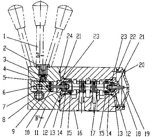
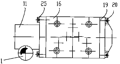
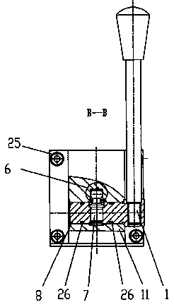
[0020] Such as Figure 1-Figure 6 As shown, the present invention schematically shows a reversing device.

[0021] The invention discloses a reversing device, such as figure 1 As shown, it includes a body 16, a front cover 11, a rear cover 19, a core assembly and a drive handle 1. The front cover 11 and the rear cover 19 are installed on the front and rear sides of the body 16, the core assembly is located inside the body 16, and the drive handle 1 The spool 17 in the driving core body assembly moves, and the spool 17 is installed in the main hole in the body 16; the two ends of the main hole of the body are equipped with screw caps 13; 25 is fixed; the right end of the body is equipped wit...


PUM


Abstract

The invention provides a reversing device, comprising a body, a front cover, a rear cover, a core assembly and a driving handle. The front cover and the rear cover are mounted at the front and rear ofthe body; the core assembly is arranged in the body; the driving handle drives the core assembly to move in a valve core; the driving handle is arranged outside the front cover and is connected withthe valve core in the core assembly via a linkage arranged in the front cover. The driving handle is arranged on one side of the front cover and is connected with a push rod via a shaft; the driving shaft drives the shaft to rotate, the shaft rotates to push the push rod via a pin to reciprocate in a main hole of the front cover, and the valve core is driven to reciprocate so that a reversing function is achieved. The driving shaft is arranged outside the front cover, so that no dust enters the front cover; an existing rubber cup can be omitted, so that the production and mounting costs are reduced; reversing resistance of the driving handle can be reduced so that good resetting effect is provided.

Description

technical field [0001] The invention relates to the field of hydraulic technology, in particular to a reversing device. Background technique [0002] Manual reversing valves are often used in hydraulic control systems to manually control the flow direction of hydraulic oil. Manual reversing valve in the prior art such as figure 1 As shown, it generally includes a body 1', a control spool 3' inside the body 1', return springs at both ends of the control spool 3', and a driving handle 2' that controls the movement of the spool 3'. Driving handle 2' is arranged on the front cover top central part, and rubber cup 21' is equipped with on the driving handle 2' bottom to block dust. However, during use, the leather cup 21' is easy to disengage, and it is easy to age in the sun and rain in the open air, thereby affecting the dustproof effect; in addition. Installing the leather cup 21' increases the reversing resistance of the driving handle at the same time. When the back pressu...

Claims


Application Information

Patent Timeline
Patent Type & Authority Applications(China)
IPC IPC(8): F15B13/02F16K11/07F16K31/60
CPCF15B13/021F16K11/0704F16K31/60
Inventor 顾婷霞
Owner 常州华睿新能源汽车发展有限公司
Learn More