
Reversing valve

A technology of a reversing valve and a four-way reversing valve, which is applied to fluid pressure actuators, servo motor components, mechanical equipment, etc., and can solve the failure of the four-way reversing valve, the leakage of the gap between the piston and the cylinder, and the reversing failure and other problems, to achieve the effect of simple structure of the main valve, reduce reversing resistance, and avoid mis-reversing

Active Publication Date: 2016-03-02
YORK GUANGZHOU AIR CONDITIONING & REFRIGERATION +1
View PDF10 Cites 0 Cited by
  • Summary
  • Abstract
  • Description
  • Claims
  • Application Information

AI Technical Summary

Problems solved by technology

[0005] Moreover, when the piston-type four-way reversing valve in the above-mentioned prior art is switched, because the pressure difference between the suction and the exhaust is relatively large, and in the process of switching, the four branch pipes will bypass, and the huge airflow sound will be relatively large. loud noise
[0006] In addition, the leakage of the piston type four-way reversing valve in the above-mentioned prior art is relatively large. On the one hand, due to the large suction and exhaust pressure difference, the gap between the piston and the cylinder will cause leakage; on the other hand, the piston Leakage also occurs in the center of the spool
[0007] In addition, in the prior art, if the unit suddenly loses power during operation, and the piston-type four-way reversing valve is in the energized state before the power failure, since the suction and exhaust pressure differences of the system will not be immediately balanced, power failure The rear four-way reversing valve will automatically reversing, which may cause the reversing failure due to insufficient power. The piston of the four-way reversing valve is in the state of four-pipe bypass, which may easily cause the failure of the four-way reversing valve

Method used


Image

  • Reversing valve
  • Reversing valve
  • Reversing valve

Examples


Embodiment Construction

[0037] In the following description, numerous specific details are given in order to provide a more thorough understanding of the present invention. It will be apparent, however, to one skilled in the art that the present invention may be practiced without one or more of these details. In other examples, some technical features known in the art are not described in order to avoid confusion with the present invention.

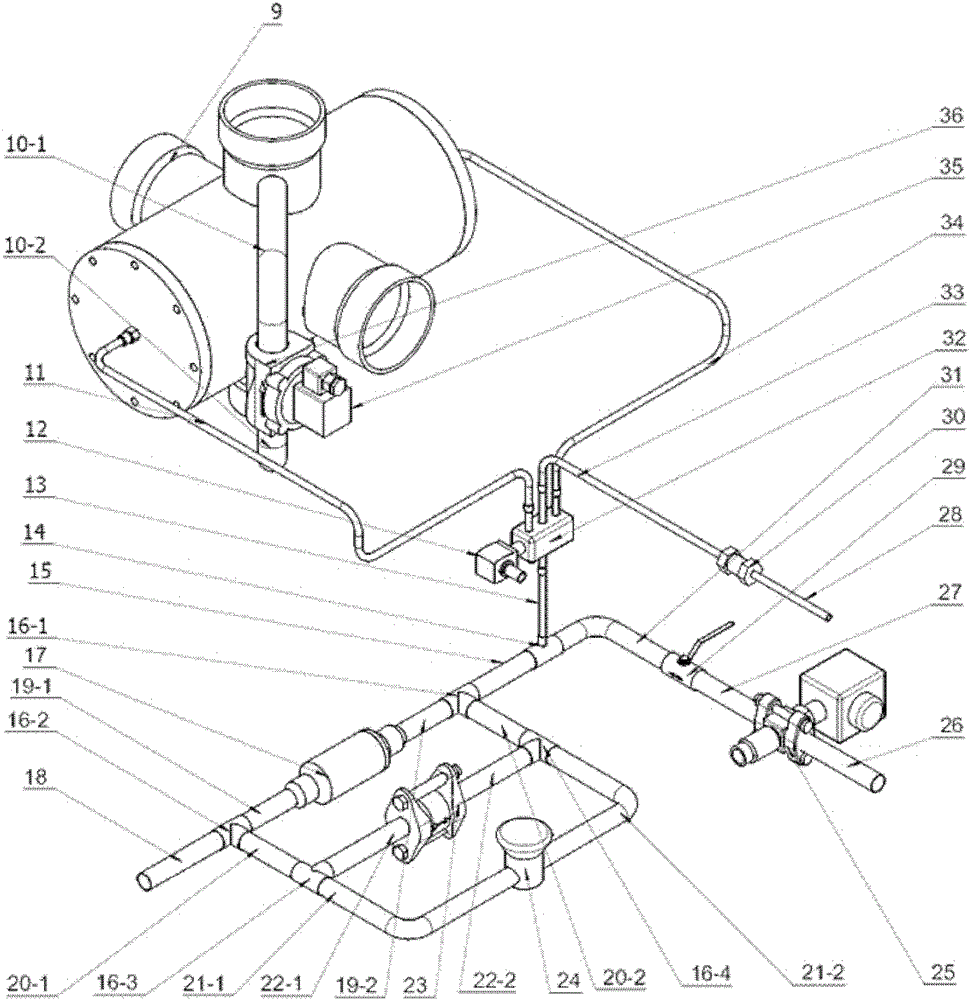
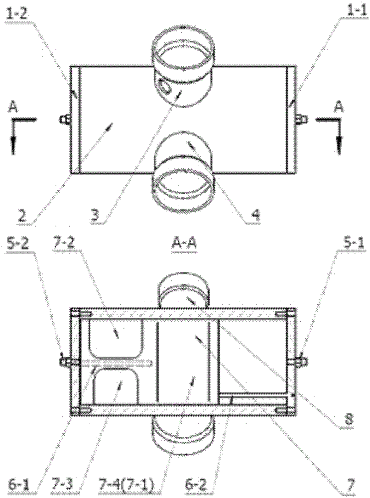
[0038] The present invention is applied in the compressor unit of the refrigeration system, and the overall system arrangement is as follows: figure 2 shown. The main components are: main valve cylinder 2, piston 7, main valve cylinder interface 3, 4, 8, 9, end cover 1-1, 1-2, joint 5-1, 5-2, pilot valve 32 and Its control coil 12, bypass solenoid valve 36 and its control coil 35, oil pump 17, check valve 30, check valve 23, back pressure valve or overflow valve 24.

[0039] Preferred embodiments of the present invention are described in detail below, howeve...


PUM


Abstract

The invention provides a hydraulically-driven four-way reversing valve and a hydraulic system thereof. The hydraulically-driven four-way reversing valve comprises a main valve and a pilot valve, the main valve comprises a cylinder body and a piston positioned in the cylinder, four mutually orthogonal connectors are arranged on the cylinder body, and the pilot valve is connected with joints on two sides of the cylinder body of the main valve through a hydraulic oil pipe. Besides, the hydraulically-driven four-way reversing valve is characterized in that the pilot valve controls hydraulic oil to flow into the left side or the right side of the cylinder body of the main valve so as to control the position of the piston in the cylinder body, and communication among the four connectors is controlled according to the position of the piston in the cylinder body. The hydraulically-driven four-way reversing valve is simple in structure, high in reliability, low in leakage rate and capable of effectively reducing reversing noise and can avoid mistaken reversing during power failure.

Description

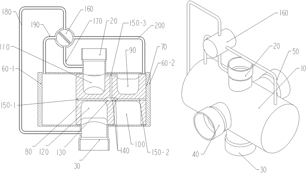
technical field [0001] The invention relates to a reversing valve used in a compressor unit of a refrigeration system, more precisely, it relates to a reversing valve with simple structure, high reliability, small leakage, which can effectively reduce reversing noise, and can avoid Hydraulically actuated 4-way directional valve for misdirection. Background technique [0002] The structure and operation principle of the piston type four-way reversing valve in the prior art are as follows: figure 1 As shown, the four-way reversing valve includes a main valve body 10, and four connecting pipes connected with the main valve body 10, that is, an exhaust pipe 20, a suction pipe 30, a first heat exchanger pipe 40 and a second heat exchanger Connector 50, end caps 60-1 and 60-2 at both ends of the main valve body 10, guide rod 70 on the end cap 60-2, piston 80 in the main valve body 10, there are two pairs of mutually perpendicular channels on the piston 80, The high-pressure chan...

Claims


Application Information

Patent Timeline
Patent Type & Authority Patents(China)
IPC IPC(8): F15B13/02
Inventor 李静陈洪升周月娴刘平
Owner YORK GUANGZHOU AIR CONDITIONING & REFRIGERATION
Learn More