
Longitudinal unfolding mechanism of missile folding rudder surface

A technology of deploying mechanisms and folding rudders, which is applied to self-propelled missiles, projectiles, offensive equipment, etc., can solve the problems that it is difficult to meet the overall outer envelope requirements, and is not suitable for airborne guided weapons, etc., to achieve compact structure and ensure aerodynamic Shape, the effect of improving the reliability of the mechanism

Inactive Publication Date: 2019-01-22
JIANGXI HONGDU AVIATION IND GRP
View PDF4 Cites 12 Cited by
  • Summary
  • Abstract
  • Description
  • Claims
  • Application Information

AI Technical Summary

Problems solved by technology

For a projectile with a large aspect ratio and a small diameter, it is difficult to meet the requirements of the overall outer envelope by lateral folding
In the existing longitudinal folding rudder surface technology, the common pyrotechnic link folding mechanism is not suitable for airborne guided weapons with small airborne guided weapons because the power source and transmission mechanism are arranged inside the missile body.

Method used


Image

  • Longitudinal unfolding mechanism of missile folding rudder surface
  • Longitudinal unfolding mechanism of missile folding rudder surface
  • Longitudinal unfolding mechanism of missile folding rudder surface

Examples


Embodiment Construction

[0012] The specific embodiments of the present invention will be further described below in conjunction with the accompanying drawings.

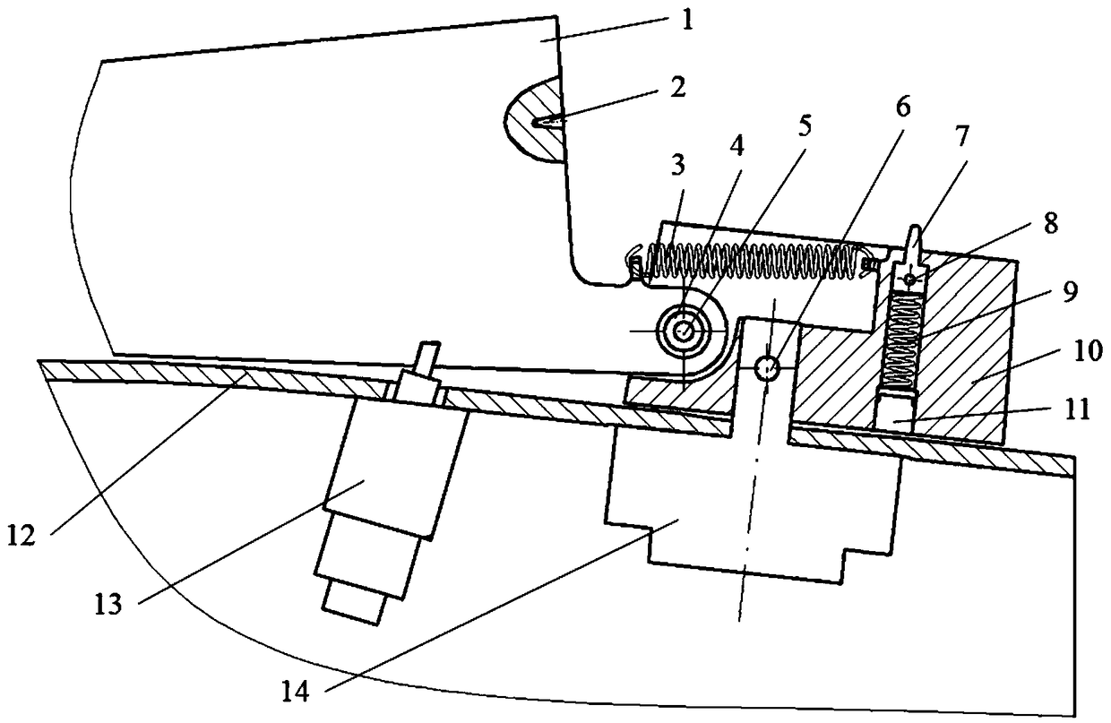
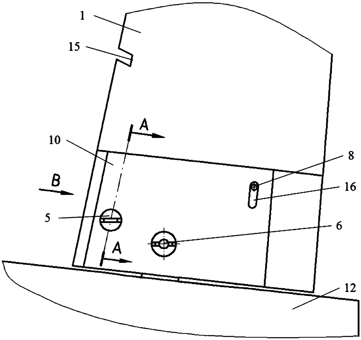
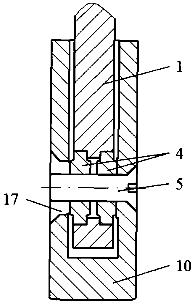
[0013] Such as Figure 1-Figure 4 Shown, a kind of specific implementation of the longitudinal deployment mechanism of the missile folding rudder surface of the present invention, the whole set of mechanism consists of a folding rudder surface 1, a tension spring 3, a bearing 4, a mandrel 5, a bolt 6, a tapered pin 7, and a compression spring 9 , fixed rudder surface 10, plug screw 11, stern compartment 12, pin puller 13, steering gear 14, nut 17 forms. Wherein the tapered pin 7, the compression spring 9 and the plug screw 11 are connected successively to form a lock in place, the root of the tapered pin 7 is a cylindrical structure, and a circular hole 8 is arranged on the side of the cylindrical body. A smooth through hole is arranged on the fixed rudder surface 10 perpendicular to its root chord surface, and the in-position lock 7 is ins...


PUM


Abstract

The invention belongs to the technical field of guided missile structure design, and relates to a longitudinal unfolding mechanism of a missile folding rudder surface. The mechanism comprises a folding rudder surface and a fixed rudder surface; the leading edge of the folding rudder surface stretches out of a rudder tiller, the rudder tiller is provided with a rotating shaft hole, and the rotatingshaft hole is provided with a bearing; the rotating shaft hole is matched with a bearing outer ring, an inner ring of the bearing cooperates with a mandrel; the folding rudder surface is connected with the fixed rudder surface through the mandrel and the bearing, and the folding rudder surface can be folded forward to the surface of a stern room around the mandrel; when the folding rudder surfaceis in a folded state, a pin puller arranged in the stern room is inserted into a square-shaped groove in the front edge of the folding rudder surface, and the folding rudder surface is locked; a tension spring is connected between the folding rudder surface and the fixed rudder surface, and after the pin puller is unlocked, the folding rudder surface is rotated to be unfolded in place under the action of the tension spring and locked by a in-position lock arranged in the fixed rudder surface. The longitudinal unfolding mechanism of the missile folding rudder surface achieves the rudder surface folding and unfolding function of a large-aspect-ratio rudder surface and small-diameter projectile.

Description

technical field [0001] The invention belongs to missile structure design technology, and relates to a longitudinal unfolding mechanism of a missile folding rudder surface. Background technique [0002] In order to facilitate the storage and transportation of airborne guided weapons and increase the ammunition capacity of the on-hook platform, folding rudder surface structures have been widely used in airborne guided weapons. Folding rudder surfaces are divided into horizontal folding and longitudinal folding according to the direction of folding movement. Horizontal folding rudder surfaces usually use torsion springs as the power source for unfolding, relying on the constraints of the launch tube wall or the pin limit of the pin puller as the initial lock, so that the rudder surface is collapsed. For a projectile with a large aspect ratio and a small diameter, it is difficult to meet the requirements of the overall outer envelope by lateral folding. In the existing longitu...

Claims


Application Information

Patent Timeline
Patent Type & Authority Applications(China)
IPC IPC(8): F42B10/64F42B15/00
CPCF42B10/64F42B15/00
Inventor 陈雷吴华晴郝桂珍万渠付俊兴瞿绍奇姚盼盼罗兵林海彬申昌富
Owner JIANGXI HONGDU AVIATION IND GRP
Learn More