
Formaldehyde detector

A technology of formaldehyde detector and outer casing, applied in the field of formaldehyde detector, can solve the problems of small size of formaldehyde detector, accidental slipping and breaking of the detector, and achieve the effect of easy dustproof and waterproof protection, convenient cleaning, and reduced occupancy

Inactive Publication Date: 2019-01-22
杭州棵林科技有限公司
View PDF0 Cites 0 Cited by
  • Summary
  • Abstract
  • Description
  • Claims
  • Application Information

AI Technical Summary

Problems solved by technology

[0004] The purpose of the present invention is to provide a formaldehyde detector to solve the problem that the existing formaldehyde detector proposed in the above background technology is small in size and easy to carry. , so as to collect air detection data. In this process, the detector may accidentally slip and cause damage. When using the detector to detect places such as construction sites, it is necessary to record detailed data while detecting, which leads to The problem of inconvenient placement of the formaldehyde detector when recording data

Method used


Image

  • Formaldehyde detector
  • Formaldehyde detector
  • Formaldehyde detector

Examples


Embodiment 1

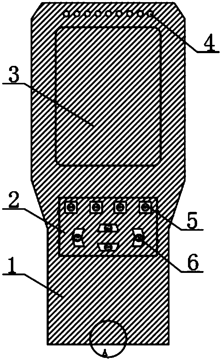
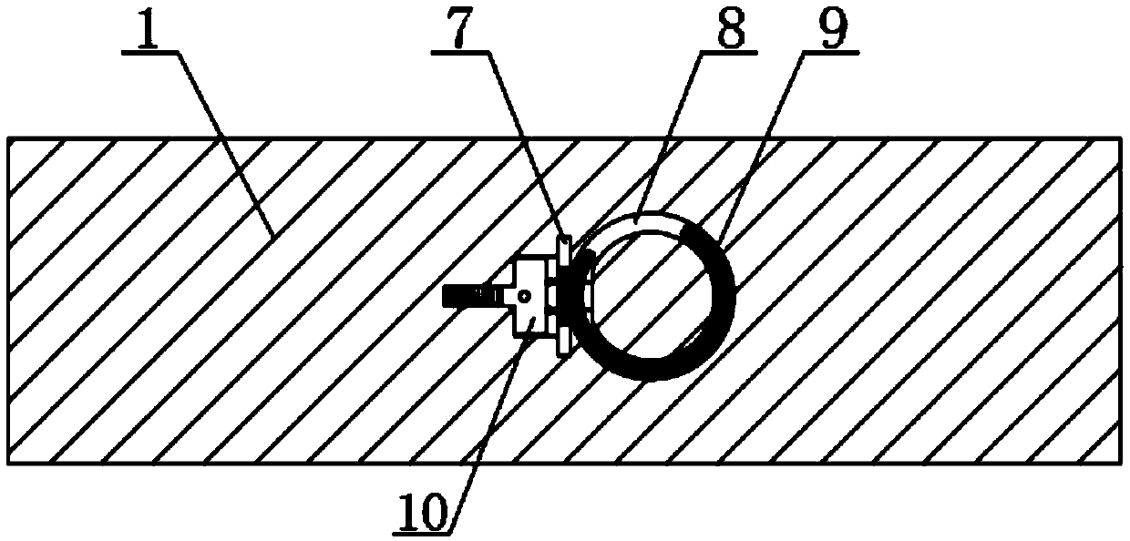
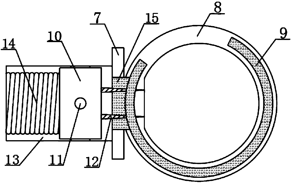
[0024] see Figure 1-Figure 6 , the present invention provides a technical solution: a formaldehyde detector, including an outer shell 1, a protective mechanism on the front surface of the outer shell 1, and a fixing mechanism on the bottom of the outer shell 1, and an air convection hole 4 is opened on the top of the front surface of the outer shell 1, and the outer shell The front surface of the body 1 is located at the bottom side of the air convection hole 4 and is provided with a display screen 3. The front surface of the outer casing 1 is located at the bottom side of the display screen 3 and is connected with a function button 5. The fixing mechanism includes a fixed plate 16, and the fixed plate 16 is provided with Two, two fixed discs 16 are connected with a rotating shaft 17, the outer surface of the rotating shaft 17 is coiled and connected with a drawstring 15, the outer surface of the rotating shaft 17 is located at the outer side of the drawstring 15, and is wound...

Embodiment 2

[0031] see Figure 1-Figure 5 and Figure 7 , the present invention provides a technical solution: a formaldehyde detector, including an outer shell 1, a protective mechanism on the front surface of the outer shell 1, and a fixing mechanism on the bottom of the outer shell 1, and an air convection hole 4 is opened on the top of the front surface of the outer shell 1, and the outer shell The front surface of the body 1 is located at the bottom side of the air convection hole 4 and is provided with a display screen 3. The front surface of the outer casing 1 is located at the bottom side of the display screen 3 and is connected with a function button 5. The fixing mechanism includes a fixed plate 16, and the fixed plate 16 is provided with Two, two fixed discs 16 are connected with a rotating shaft 17, the outer surface of the rotating shaft 17 is coiled and connected with a drawstring 15, the outer surface of the rotating shaft 17 is located at the outer side of the drawstring 1...


PUM


Abstract

The invention discloses a formaldehyde detector. The formaldehyde detector comprises an outer shell, a protective mechanism at the front surface of the outer shell, and a fixed mechanism at the bottomof the outer shell, wherein the top of the front surface of the outer shell is provided with an air convection hole, a display screen is arranged at the bottom of the air convection hole on the frontsurface of the outer shell, a functional button is connected at the bottom of the display screen on the front surface of the outer shell, and the fixed mechanism comprises a fixed disk. The fixed mechanism enables the detector to be suspended on a belt conveniently, so that a user can record data while detecting, and the suspended detector does not slide accidently so as not to be damaged; in addition, the length of a pull belt can be regulated freely according to different suspension heights; a packable suspension loop occupies less external space; and the protective mechanism protects the functional button of the detector from dust and water, and is convenient to clean due to the detachable design of the protective mechanism.

Description

technical field [0001] The invention belongs to the technical field of formaldehyde detection, in particular to a formaldehyde detector. Background technique [0002] The formaldehyde detector is an instrument for detecting formaldehyde. It has the advantages of small size, easy to carry and use, and the detection speed is fast, and the detection structure can be displayed intuitively. The formaldehyde detector is widely used in the real-time detection of formaldehyde in the air of living rooms, indoors, residential areas, public places, and living places. [0003] The existing formaldehyde detector is small and easy to carry. When using the detector to detect the air in many places in the room, it is necessary to walk around with the detector in hand to collect air detection data. During this process, the detector may have accidents The problem of falling caused by falling, and when using the detector to detect the construction site and other places, it is necessary to rec...

Claims


Application Information

Patent Timeline
IPC IPC(8): G01N33/00
CPCG01N33/0009
Inventor 来丽琳
Owner 杭州棵林科技有限公司
Learn More