Zero position calibration method and device for mechanical arm joint sensor

A calibration method and technology for calibrating equipment, applied in manipulators, manufacturing tools, etc., can solve problems such as high cost and large installation space, and achieve the effect of improving efficiency, improving measurement efficiency, and simplifying measurement equipment and measurement process.

Active Publication Date: 2019-01-25
CHINA RAILWAY CONSTR HEAVY IND
View PDF6 Cites 6 Cited by
  • Summary
  • Abstract
  • Description
  • Claims
  • Application Information

AI Technical Summary

Problems solved by technology

[0002] In the application of construction machinery, the following method is often used when performing joint sensor zero correction on machines such as mine wet spraying machines: the angle of the mechanical arm joint is measured by a rotary encoder or a decoding device using a single resolver, It is realized by comparing the angle measured by the device with the data fed back by the sensor, but these devices have high cost and large installation space, which has great limitations.

Method used


Image

  • Zero position calibration method and device for mechanical arm joint sensor
  • Zero position calibration method and device for mechanical arm joint sensor
  • Zero position calibration method and device for mechanical arm joint sensor

Examples


no. 1 example

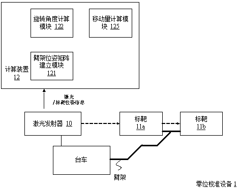
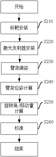
[0087] figure 1 It is a structural schematic diagram of Example 1 of the zero position calibration device of the robot arm joint sensor of the present application, figure 2 It is a schematic flowchart of Example 1 of the zero calibration method for the joint sensor of the manipulator of the present application. Refer below figure 1 with figure 2 This example will be described.

[0088] Such as figure 1 As shown, the zero calibration equipment 1 includes a computing device 12, a laser emitter 10 and two targets 11a and 11b arranged on a trolley. Wherein, a pattern is provided on each target, and in this example, the pattern is preferably roughly in the shape of a "ten", such as a solid cross "┼" (see Figure 7 (A) left picture), of course, in addition to the solid cross, it can also be a hollow cross "╬" (cf. Figure 7 (A) Right panel). During the calibration process, the two targets 11a and 11b are installed in parallel on the set end arm of the mechanical arm to b...

no. 2 example

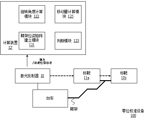
[0128] image 3 It is a structural schematic diagram of Example 2 of the zero position calibration device of the robot arm joint sensor of the present application, Figure 4 It is a schematic flow chart of Example 2 of the zero calibration method for the joint sensor of the manipulator of the present application. Also refer to below image 3 with Figure 4 This example will be described.

[0129] Such as image 3 As shown, the zero calibration device 100 includes a computing device 12', a laser transmitter 10 and two targets 11a and 11b arranged on a trolley. In this example, the laser emitter 10 and the targets 11a and 11b used are generally consistent with the first embodiment, and a cross laser emitter (the laser spot is in the shape of a "cross") and a "cross" pattern in the center is also used. Target. Computing device 12 ′, except possessing functions substantially consistent with computing device 12 of the first embodiment, also includes a judging module 123, and ...


PUM


Abstract

The invention discloses a zero position calibration method and device for a mechanical arm joint sensor. The method comprises determining whether a mechanical arm to be tested is a redundant mechanical arm, if so, performing mechanical arm segmentation and using a non-redundant boom as a set end arm, and performing the steps of the following single calibration method until zero calibration of allthe joints of the mechanical arm to be tested is completed; mounting at least two targets in parallel on the set end boom and keeping matching elements of patterns of the targets in parallel; mountinga light source on a mechanical arm mounting body; driving movement of the joints of the mechanical arm to make a beam of the light source pass through the axis of each target with the spot overlappedwith the pattern of each target; obtaining the posture of each target after the boom posture is adjusted and calculating the rotating angle of the rotating joints of the mechanical arm and the movingamount of the moving joints under the current posture of the set end boom according to the relationship between the posture of the set end boom and the posture of the light source. Compared with theprior art, the method is simpler and more efficient when used for performing zero calibration.

Description

technical field [0001] The invention relates to the field of engineering machinery, in particular to a zero calibration method and equipment for a joint sensor of a mechanical arm. Background technique [0002] In the application of construction machinery, the following method is often used when performing joint sensor zero correction on machines such as mine wet spraying machines: the angle of the mechanical arm joint is measured by a rotary encoder or a decoding device using a single resolver, Then, it is realized by comparing the angle measured by the device with the data fed back by the sensor, but these devices have high cost and large installation space, and have great limitations. Contents of the invention [0003] One of the technical problems to be solved by the present invention is to provide a simple and efficient zero calibration method and equipment for the joint sensor of the mechanical arm. [0004] In order to solve the above-mentioned technical problems, ...

Claims


Application Information

Patent Timeline
Patent Type & Authority Applications(China)
IPC IPC(8): B25J19/00
CPCB25J19/0095
Inventor 刘飞香郑大桥秦念稳李建华李庆仁小强王华明王鹏翔王斌周俊宇
Owner CHINA RAILWAY CONSTR HEAVY IND
Why Eureka
Try Eureka