
Spacecraft off-orbit electrodynamic tethers

A technology of off-orbit electricity and spacecraft, which is applied in the field of spacecraft off-orbit, can solve the problems of not taking into account the reliability and the convenience of analysis and calculation, the instability of the space state of the electric power tether, and the inaccurate analysis of spacecraft kinematics, etc. , to achieve the effects of convenient theoretical analysis and model calculation, convenient modeling, and simple state control

Active Publication Date: 2020-04-24
BEIHANG UNIV
View PDF7 Cites 0 Cited by
  • Summary
  • Abstract
  • Description
  • Claims
  • Application Information

AI Technical Summary

Problems solved by technology

Since the thinner electrodynamic tethers are used in the on-orbit tests and theoretical studies, the length of the tethers in space may vary from hundreds of meters to hundreds of kilometers. The shape and state of the tethers It will change with the change of the external force. The tether cuts the earth’s magnetic field line in the space environment. Gravity gradient force and Lorentz force act on the electrodynamic tether with a certain length, which will make the space of the electrodynamic tether The state becomes unstable, and the kinematic analysis of the spacecraft as a whole will become inaccurate
[0005] On the other hand, when conducting theoretical research and de-orbit simulation, it is necessary to establish a theoretical model for the electrodynamic tether. The existing tether models include rigid rod model, elastic rod model, chain rod model, and bead model. model, continuum model, etc. The closer the model selection is to the actual situation, the more complex the calculation process will be. However, the existing models cannot take into account the good accuracy and the convenience of analysis and calculation.

Method used


Image

  • Spacecraft off-orbit electrodynamic tethers
  • Spacecraft off-orbit electrodynamic tethers

Examples


Embodiment Construction

[0025] The specific implementation manners of the present invention will be further described in detail below in conjunction with the accompanying drawings and embodiments. The following examples are used to illustrate the present invention, but are not intended to limit the scope of the present invention.

[0026] In the description of the present invention, it should be noted that the terms "center", "longitudinal", "transverse", "upper", "lower", "front", "rear", "left", "right", " The orientations or positional relationships indicated by "vertical", "horizontal", "top", "bottom", "inner", "outer", etc. are based on the orientation or positional relationships shown in the drawings, and are only for the convenience of describing the present invention and simplifying Describes, but does not indicate or imply that the device or element referred to must have a specific orientation, be constructed in a specific orientation, and operate in a specific orientation, and therefore sh...


PUM


Abstract

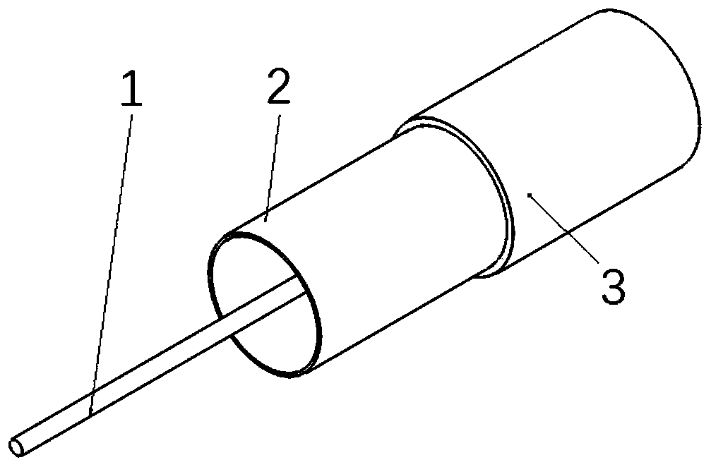
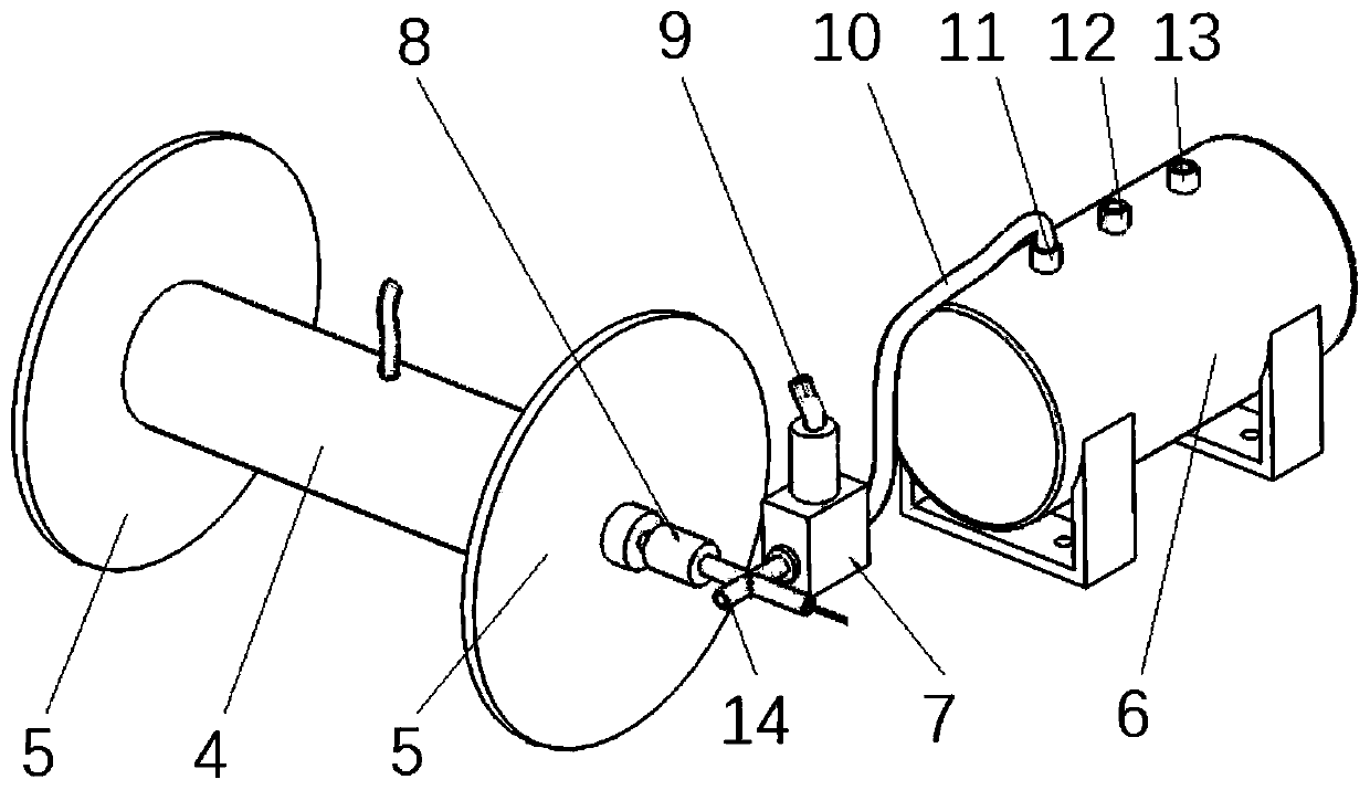
The invention relates to the technical field of spacecraft deorbiting, and discloses a spacecraft deorbiting electrodynamic tether, comprising an electrodynamic tether and a charging and degassing device, wherein the electrodynamic tether comprises a conductive wire and an elastic layer sleeved outside the conductive wire, and the charging and degassing device is connected with the electrodynamictether for charging and degassing into the elastic layer. The invention provides a spacecraft deorbiting electrodynamic tether, the elastic layer sleeved outside the conductive wire is inflated by aninflating / deflating device, so that the elastic layer becomes an air column with an internal air pressure and a certain stretching tension, thus, the electrodynamic rope becomes a rod with certain bending and torsional stiffness in space, which improves the stability of the electrodynamic rope in space, avoids the problem that the effective length of the rope decreases due to the backward folding,does not need to consider the disturbance of the axis direction of the rope, and makes the state control of the electrodynamic rope relatively simple. In addition, it is convenient to model, which makes the electrodynamic tether more convenient and concise in theoretical analysis and model operation.

Description

technical field [0001] The invention relates to the technical field of spacecraft de-orbiting, in particular to a spacecraft de-orbiting electric power tether. Background technique [0002] With the continuous increase of human space activities, the space above the earth is becoming more and more crowded, and the number of satellites and space junk is increasing day by day. According to statistics, there are currently more than 4,300 artificial satellites orbiting the earth, of which only more than 1,200 are in normal operation. A large amount of space junk, including abandoned satellites, has seriously affected the development of human space activities, not only occupying precious orbital resources, but also bringing great uncertainty and security threats to the normal operation of orbiting spacecraft. The size of space debris ranges from millimeters to tens of centimeters. Collisions between them and collisions between existing debris and satellites will generate more new...

Claims


Application Information

Patent Timeline
Patent Type & Authority Patents(China)
IPC IPC(8): B64G1/66
CPCB64G1/66
Inventor 师鹏雷冰瑶刘思帆程琦翔赵育善
Owner BEIHANG UNIV
Learn More